Sous vide is the method of cooking food in airtight bags using a water bath at a precise temperature.
The method is fantastic to get the meat and seafood cooked evenly at the cooking point you love most.
http://modernistcuisine.com/2013/01/why-cook-sous-vide/http://www.douglasbaldwin.com/sous-vide.html
Buying an off the shelf sous vide can run for several hundreds of dollars. One of the many ways you can explore the world of modernist cooking is with your raspberry pi / some sensors and extra electronics/mathematica and a crock pot.
This initial posting will cover the very basic building blocks necessary for connecting to temperature gauges needed + turning on/off the crock pot.
I hope that through the community postings we can all develop a full fledge solution using the Raspberry Pi that can allow you to monitor the temperature of the water bath, food, setting up the off/on temperatures, chart the cooking process, send SMS text /email when food is done, etc.
Let's start with the basics.
We'll need to turn on/off the water bath (crock pot). For that we'll need to control a relay.
You can build your own circuit. Gaven McDonald's instructional video is a great starting point to build your own circuit and check how to connect the relay to your Raspberry Pi.
https://www.youtube.com/watch?v=b6ZagKRnRdMYou can buy a 2-relay module that works for Arduino/Raspberry just like this one.
http://www.sainsmart.com/arduino/arduino-components/relays/arduino-pro-mini.html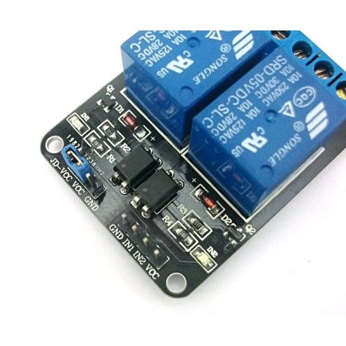
Opening/Closing the relay is straightforward with Mathematica. Using one of the available pins (ie PIN 17) you can power on /off the crockpot by using the command
DeviceWrite["GPIO",17->1]
Things get a little bit more challenging with taking temperature readings from the thermocouples.
As BobtheChemist pointed out in his blog
http://www.bobthechemist.com/index.php/10-stuff/24-thanksgiving-pi
The raspberryPi does not have analog pins in its GPIO (General Purpose Input Output). In his blog entry Bob shows how to overcome this limitation by using a capacitor and measuring how long it takes to charge it.
For this entry, I decided to document the use of an analog to digital converter (ADC).
Checking out the web I found from several discussions and postings that the MCP 3008 would do the job.
http://www.adafruit.com/products/856
We can use this transistor to hook up up to 8 analog sensors into our project. In our case, we'll only need two. One for the water bath probe and another for the food probe.
The following wire diagram covers how to connect the MCP 3008 to the GPIO (Please focus on the right side of the MCP3008 wiring).
http://learn.adafruit.com/reading-a-analog-in-and-controlling-audio-volume-with-the-raspberry-pi/connecting-the-cobbler-to-a-mcp3008For the thermocouples, you need to watch out on the type of thermocouples you get.
For this specific project the replacement probes for the Maverick ET-73 will work just fine.
http://www.amazon.com/gp/product/B004W8B3PC/ref=oh_details_o00_s00_i00?ie=UTF8&psc=1The thermocouples must be connected to the MCP3008 channels CH0 and CH1 in the following manner.
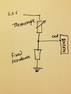
We do need to determine the value needed for the fixed resistance. The best value would be equal to the one expected when we reach the cooking temperatures. As I like my steaks medium I chose 60C as the point to use.
Using a thermometer, the thermocouples and a multimeter, I measured the temperature of a ice water glass, hot water and warm water. Using the three points, we can find the function that represents the temperature based on the resistance of the thermocouple.
temp = {20.6, 42, 83.3} + 273.15
resistance = {220650., 95800., 26340.}
data = Transpose[{Log@resistance, Log@temp}]
lm = LinearModelFit[data, x, x]
lm[{"RSquared"}]
The model fits very well R^2=0.998
What is the expected resistance at 60C?
invdata = Transpose[{Log@temp, Log@resistance}]
Fit[invdata, {1, x}, x]
(*74.3895 - 10.9297 x*)
f[x_] := 74.38949510675315` - 10.929736543045369` x
Exp[f[Log[60 + 273.15]]]
(*54344.9*)
Thus I used 56K Resistors for the thermocouples.
Now, to the function needed to read the thermocouples value. We have to probe the analog inputs from the MCP 3008 via the GPIO.
We can use the library for the MCP 3008 developed by Gabriel Perez-Cerezo
http://gpcf.eu/projects/embedded/adc/There are two libraries needed gpio.h and mcp3008.h.
Dropped them both into /usr/include directory in the Raspberry Pi
The other very important step necessary is exporting the GPIO pins into /sys/class/GPIO, Gabriel also provides the script needed in hist web page. Please make sure to follow his intructions found in the comment section of the script. I forgot to run the
update-rc.d -f gpio defaults command after the installation and spent quite of bit of time after rebooting the equipment several days later. Was getting an error in Mathematica (and a c program to check if the reading was working, kept getting a segmentation fault error) all because the step needed for the script to run at startup was not in place.
Once we have the libraries in place we can address building a function with MathLink to get the readings from the MCP 3008
Please refer to the mathlink developer guide for more details in how it works
http://reference.wolfram.com/mathematica/tutorial/MathLinkDeveloperGuide-Unix.htmlBuilt the two files needed for the function
adc.tm
:Begin: adc
:Pattern: adc[adc_Integer, clock_Integer, in_Integer, out_Integer, cs_Integer]
:Arguments: {adc, clock, in, out, cs}
:ArgumentTypes: {Integer, Integer, Integer, Integer, Integer}
:ReturnType: Integer
:End:
adc.c
#include <mathlink.h>
#include <mcp3008.h>
int adc(int adc, int clock, int in, int out, int cs) {
return mcp3008_value(adc, clock, in, out, cs);
}
int main(int argc, char *argv[]) {
return MLMain(argc, argv);
}
After creating both files, I proceeded to compile the program with the following command.
This generated the necessary function that can now be invoked from Mathematica or the wolfram engine as follows.
Install["/home/pi/mathematica/adc/adc"];
(*We can now call function adc to read the voltage drop at the thermocouple
The voltage reading will be read by the MCP as a value between 0 (0V)to 1023 (3.3V) *)
(* Analog Channel = 0, ClockPin = 18, In = 23, Out =24, CS = 25 *)
adc[0, 18, 23, 24, 25]
(*The following function translates the voltage reading to temperature in Celsius*)
temp[channel_] :=
Module[{R2 = 56000, a = -0.0913946, b = 6.80504, R1,
x = adc[channel, 18, 23, 24, 25]},
R1 = (1024 - x) R2/x ; Exp[a Log[R1] + b] - 273.15]
(*Function datapoints is used to collect temperature readings in a matrix of length maxPoints. It also controls the relay
to turn on the crockpot when the temperature reading is below the setpoint and turn it on when above the set point*)
datapoints[myList_List, fn_, maxLength_Integer, setPoint_Integer] :=
Module[{x, val = fn},
x = Append[myList, {DateList[], fn}];
If[val < setPoint, DeviceWrite["GPIO", 17 -> 0],
DeviceWrite["GPIO", 17 -> 1]];
If[Length[x] > maxLength, x = Take[x, -maxLength], x]]
data={};
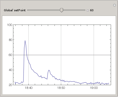
(*Using a Chart to establish the setpoint and graph the temperature trend *)
Manipulate[
DateListPlot[Refresh[data = datapoints[data, temp[0], 300, setPoint],
UpdateInterval -> 15, TrackedSymbols -> {}], Joined -> True,
PlotRange -> {Automatic, {20, 100}},
GridLines -> {Automatic, {setPoint}}], {{setPoint, 60}, 30, 80, 1,
Appearance -> "Labeled"}]
This is a link to the video that shows the program running and controlling the relay.
http://youtu.be/4ae42ctVZukNext challenge will be to use the Web Server functionality of the Raspi to interact with Mathematica so as to control the set point and chart the temperature curve via a web page.
... to be continued.


