This post will demonstrate how to talk with an Arduino Uno over a serial connection using the Wolfram Language. This is an updated version of this post.
The following hardware is necessary:
First we need to upload the following sketch to the Arduino Uno so that it will listen over serial for commands from the Wolfram Language.
void setup()
 {
   Serial.begin( 115200);
   for(int i=2;i<10;i++) {
     pinMode(i,OUTPUT);
   }
 }

void loop()
{
  if( Serial.available()>=2)
  {
    int pin = Serial.read();
    int value = Serial.read();
    digitalWrite( pin, value);
  }
}
This configures the Arduino to expect a pair of byte values. The first is a pin Number, (from 2 to 9) and an on/off value (0 or 1).
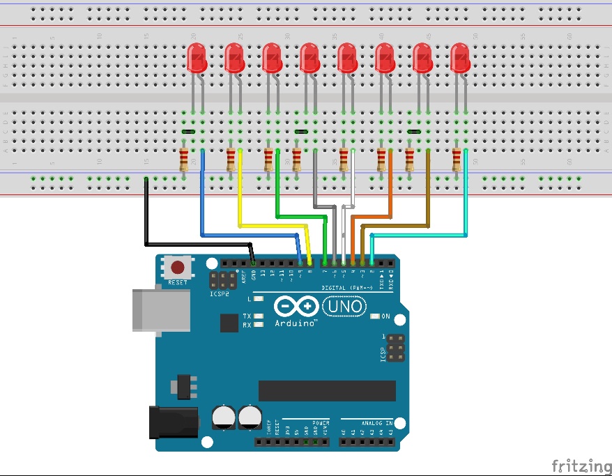
Now configure the Arduino as shown below in the Fritzing diagram. Connect each LED to a resistor and a pin from the Arduino.
Now connect the Arduino to your Raspberry Pi (or alternatively you can connect it directly to your computer with Mathematica 10). On the Raspberry Pi the default serial port is "/dev/ttyACM0", but on Windows or Mac it will be different. One easy way to find the correct serial port is to open up the Arduino software and under Tools -> Serial Port will be a list of serial ports the Arduino could be on.
On the Raspberry Pi, start up the wolfram engine by typing:
pi@raspberry-wri2 ~ $ wolfram
Then run the following command to open the Serial port (note to change the serial port if not on a Raspberry Pi):
DeviceWrite[serial,{pinNumber,val}]
pinNumber should be between 2 and 9, and val should be 1 to turn the LED on, and 0 to turn it off. The following code will blink each LED on in turn.
Do[(
DeviceWrite[serial,{pinNumber,1}];
Pause[1];
DeviceWrite[serial,{pinNumber,0}];
Pause[.2]),
{pinNumber, Range[2,9]}]


