Hi Bruce Woods!
The boolean connector of the ideal switch is actually an array of 3 different boolean connectors. I have never used the Electrical.MultiPhase library but I would guess that each of these connectors correspond to opening and closing of the individual phase connection. If you want each phase to be controlled by the same input you got a couple of options. You could place a BooleanStep block and make a connection 3 times and for the first connection specifying the indices 1, then 2 and finally 3.
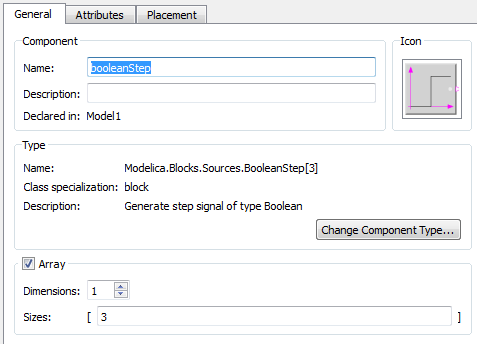
In the AIMC_DOL example they have gone another route. There they have specified the BooleanStep block as being an array of m (for you, m would be 3) individual blocks. Then they map each of their output to a corresponding input. You can make your block an array by selecting the block and pressing F2 and at the bottom of the window you should find a checkbox that says array. Check it and in sizes, write 3.
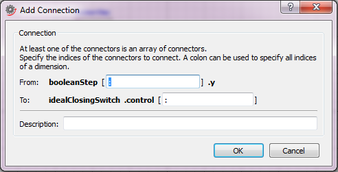
Then you can connect it to the connector on the closing switch. If the dimensions of the two connectors match, you can write ":" in both of the fields. This will map all the connectors together.
If you don't want the input into the closing switch to be same, you can give your array block different parameter values for each of the blocks. For your Boolean steps you could for example write {0, 1, 2} in the field next to startTime which would cause the switch for the first phase to close at time 0, at time 1 for the second phase and at time 2 for the third phase. Alternatively you could connect three different boolean blocks to each of the connectors, a pulse to one phase, an table to another and so on, by specifying the indices for the corresponding phase!
As a side note, it is always easier to give a more complete answer if you attach the code you have tried.
Hope that helps!
Patrik


