Message Boards Message Boards

0
|
13384 Views
|
26 Replies
|
2 Total Likes
View groups...
Share
Share this post:

How to build a loop for a convergence (centroid calculation)

I would ask for some help to implement a code to be able to find the center of mass of an annular image of light projection from a fiber optics. The center of mass should be the point where it originates the average radius. On the other hand, the average radius ends at the point, inside the annulus, where the light intensity is maximum. Basically, an initial center is chosen (may be the center of the frame), then 18 sectors are built from that center to the larger circle of the annulus, which is contained in the frame. The fix for the assumed center is calculated as the sum of the average radius times the cosine (in x) and sine (for y) sectors around the circle. The center is shifted to there and the process repeated. In another words, the new coordinates obtained, original center plus delta x and delta y, must to shift the original center closer to the correct center of mass. However the operation should be performed some times until convergence is complete or that the residual value is less than or equal to 1 pixel. This should probably happen after two or three interactions, depending of course the amount initially chosen for the original center. So far, the current code is able to find the value delta x and delta y to be added to the center originally preset. My difficulty is define a loop to redo the operation as many times as necessary. I would really appreciate some help to finish this code to obtain the final value of the center of mass coordinates. Thanks for any help...

Attachments:
26 Replies
Posted 8 years ago

Antonio, Are you working on the Subaru spectrograph? Can you perhaps send me the paper you mentioned? You can find my email on my web site listed in my community profile.

Kind regards, David

POSTED BY: David Keith
Posted 8 years ago

Hi Antonio,

Yes, the second part is still connected, and the symbol "files" has a value which is the list of file names. I reused the name "files" in the argument to the analyzeImageGroup function, which was a bit confusing. But appearing as an argument it is a formal parameter, and not the same. The function accepts a list of file names, which are still available as the value of the global symbol "files." But when used, analyzeImageGroup just expects a list of file names, each being a string. In the notebook, these are given without full paths because we have already set the default directory to the notebook directory, and the files are in it.

Here is some code which was executed after the notebook was executed. Notice that files still has a value which is our full list of file names. But I can also give the function a list of file names I have typed in. And I can also Map the function onto a list of lists, where each bottom level list is a list of file names. Now I get a list of analysis results, one result for each of the bottom level list of file names. This could be used to process an entire set of data, consisting of separate lists for each group of images which should be added and analyzed.

In[63]:= files

Out[63]= {"fiber3_0.fits", "fiber3_1.fits", "fiber3_2.fits", \
"fiber3_3.fits", "fiber3_4.fits"}

In[64]:= analyzeImageGroup[files]

Out[64]= {{476.983, 500.031}, 386.469, {"fiber3_0.fits", 
  "fiber3_1.fits", "fiber3_2.fits", "fiber3_3.fits", "fiber3_4.fits"}}

In[65]:= (* Here we explicitly give it a list of file names *)

In[66]:= analyzeImageGroup[{"fiber3_1.fits", "fiber3_2.fits"}]

During evaluation of In[66]:= InterpolatingFunction::dmval: Input value {0.652631,498.308} lies outside the range of data in the interpolating function. Extrapolation will be used. >>

During evaluation of In[66]:= InterpolatingFunction::dmval: Input value {0.176204,498.308} lies outside the range of data in the interpolating function. Extrapolation will be used. >>

During evaluation of In[66]:= InterpolatingFunction::dmval: Input value {-0.300222,498.308} lies outside the range of data in the interpolating function. Extrapolation will be used. >>

During evaluation of In[66]:= General::stop: Further output of InterpolatingFunction::dmval will be suppressed during this calculation. >>

Out[66]= {{471.156, 498.285}, 387.422, {"fiber3_1.fits", 
  "fiber3_2.fits"}}

In[67]:= (* The errors are not a problem, but can be turned off if we \
want *)

In[68]:= Off[InterpolatingFunction::dmval]

In[69]:= analyzeImageGroup[{"fiber3_1.fits", "fiber3_2.fits"}]

Out[69]= {{471.156, 498.285}, 387.422, {"fiber3_1.fits", 
  "fiber3_2.fits"}}

(* We can Map the function onto a list of lists to get a list of \
results *)

In[70]:= listOfLists = {{"fiber3_1.fits", 
    "fiber3_2.fits"}, {"fiber3_3.fits", "fiber3_4.fits"}};

In[71]:= analyzeImageGroup /@ listOfLists

Out[71]= {{{471.156, 498.285}, 
  387.422, {"fiber3_1.fits", "fiber3_2.fits"}}, {{473.682, 500.875}, 
  386.866, {"fiber3_3.fits", "fiber3_4.fits"}}}

(* Turn the error message back on *)
POSTED BY: David Keith

David, I understand the FileNames function. I don't understand how this function work in the notebook, second part of Cesar1_2 output deleted.nb. There is some dependence between the first part with the second part? When I use the second part, some thing looks like connected with the first part. The FilesNames function was defined only in the first part, not in the second. What is this?

Antonio

Posted 8 years ago

Hi Antonio,

Just about the first line in the notebook uses FileNames function to generate a list of the file names as strings and assign the list to the symbol files. But any method that generates such a list would work the same. You could also Map the analysis function onto a list of lists to analyze severa groups of files.

Yes. I would love to see the paper. You could attach it or send it to my email.

Best, David

POSTED BY: David Keith

Hi David, Everything is working as it should now. But I still have one doubt regarding automated code. The doubt is: How does the Code knows which files will be read? We don't give any information except by the word "files". Sorry, perhaps may be an idiot question.........

PS: If you want to know more about this experiment I can send my paper about...

Posted 8 years ago

Hi Antonio, How this happens depends on which plotting function you use to display the image. Mathematica ListPlot and ContourPlot and similar functions plot f[x,y] with x on the horizontal and y on the vertical, increasing left to right and bottom to top as usual. But ArrayPlot and similar functions plot array[[row,column]] with rows on the vertical axis, increasing top to bottom, and columns on the horizontal, increasing left to right. (Edit: It looks like the graphic of an image, as when it is first imported, is oriented like the graphic plotting routines, not like ArrayPlot.)

So if we build an interpolating function with the row and column indices in the x and y position we get this rotation, and ListInterpolation will do this.

temp = {
   {1, 1, 0, 0, 0},
   {1, 1, 0, 0, 0},
   {0, 0, 0, 0, 0},
   {0, 0, 0, 0, 0},
   {0, 0, 0, 0, 0}};

tf = ListInterpolation[temp];

ContourPlot[tf[x, y], {x, 1, 5}, {y, 1, 5}, PlotLegends -> Automatic]
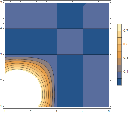
enter image description here

This could be overcome by building the Interpolating function differently. Also, ArrayPlot has an option that helps. (Note that ArrayPlot inverts intensity to create a negative image.) Here Transpose swaps rows for columns, and DataReversed plots bottom to top.

ArrayPlot[temp // Transpose, DataReversed -> True]

enter image description here

Best,

David

POSTED BY: David Keith

Hi David, I think I understand what's going on. Everything is working properly. However, after the interpolation operation the image is rotated 90 degrees counterclockwise. This is the cause of the anomaly. Note the image before and after the interpolation operation ...... If we discount this effect everything is perfect. In principle I do not know how to fix this effect. Could you do?

Antonio

Posted 8 years ago

Hi Antonio, I looked at the file I sent earlier (Cesar 1_2.nb) and used Get Coordinates on the original summed image. I can't say my guess at a center was good, but when I put the cursor at the center determined by the algorithm I get matching values. What are you seeing?

Best, David

PS: What makes the ring?

Get Coordinates:

enter image description here

The calculated center:

enter image description here

POSTED BY: David Keith

Hi David,

I have done the convergence calculating repeating the process manually until the correction come. It does not reach below 0.25, at least within a reasonable time. But reaches below 0.5. The numbers fluctuate around 1. The explanation may be due to image noise as you suggest. However, the difference in the width of the ring and its intensity variation is characteristic of the polishing angle of the fiber. This experiment serves to measure this effect. If the optical fiber is polished so that the surface is perfectly perpendicular to its optical axis, the angular deviation is zero, and the ring is perfectly symmetrical. Obviously this is not the case. What worries me is the fact that I have manually measured the coordinates of which is supposed to be the center of the image and I always get something like (495, 530). Please, if you have some time try this using the obtaining coordinate tools.

Thanks,

Antonio

Posted 8 years ago

Hi Antonio,

I think convergence will be influence by the image data. With sufficiently noisy the process could just wander around. A choice of a center produces a set of maxima, which produces a different center, etc. There could be patterns that even cycle without convergence. For sufficiently noisy image data we might be just wandering until we happen to get 2 centers in a row which are sufficiently close. But the process really doesn't converge in a continuous way. It might converge better for smoothed data, but then you have to ask if that particular converged result is really better than one of the results from acting on non-smoothed data.

I was looking at a different calculation which might be interesting. I calculate the set of maxima around the ring as before. But instead of calculating a center from the XY positions, I use the XYZ positions and fit to a plane. The Z is the image intensity. It is interesting the way the ring is sharp and intense toward one side, and broader and less intense toward the other. One possible explanation is that it is as an object more uniform, but in the imaging system it is tilted with respect to the optical axis -- so the broader less intense side is really just out of focus.

This "tilt" is of course just a parameter. The X and Y is in units of pixels (which are distance), and the Z is in intensity, which is in different units, so ArcTan of intensity divided by distance is a rather strange thing.

Here is a code snippet. It calculates a tilt of almost 1 degree for the plane fitting the maxima:

In[33]:= fit = LinearModelFit[centeredMaxima, {x, y}, {x, y}];

In[34]:= parameters = fit["BestFitParameters"]

Out[34]= {-2.91103*10^-17, 0.00012698, -0.00154588}

In[35]:= tilt = Norm[parameters[[{2, 3}]]]/Degree

Out[35]= 0.0888707

In[36]:= fitFunction = fit["BestFit"]

Out[36]= -2.91103*10^-17 + 0.00012698 x - 0.00154588 y

Here is a set of maxima and the best fit plane:

enter image description here

POSTED BY: David Keith

Dear David, At first I would like to thank you for your effort and time spent to prepare and explain so thoroughly your code suggestion. I consider that I learned many new tricks with it. During the last days I broke your code and reassembled the minimal form just to get the centroid coordinates. The algorithm works within the suggested process. However I have noted that the "Norm" does not converge to an infinitely small number. In fact, when you limit the stopping point at 0.25 pixels the looping continues forever. In fact the lower value of "Norm" is around 1.24 pixels. Thereafter, "Norm", begins to grow again. I don't know if this is a mathematical problem or an anomaly within the code. I'm going to continue the investigation in the coming days.

Thanks,

Antonio

Hi David, I need more time to evaluate your latest code. So far I could take apart and understand your previous code almost completely. I have not a final conclusion yet. I can say that the code seems to work as it should and that their algorithm seems ok. However, I'm not too sure about the result, I need to continue investigating. Give me some more days......

This experiment is not confidential, You can ask what you want. This is a situation in which light from a laser is incident on the input fiber with an angle to the surface. The result is that the output light is a ring-shaped projection. The image that you see, is obtained with the help of a beam spliter reflecting the ring projected onto a target at about 1 meter from the output of the fiber. The analysis of the results can give us informations about the polishing angle of the fiber in test.

Thanks a lot.....

Best regards,

Antonio

Dear David,

If you are fascinated, I feel good to go a little deeper in the understanding of this problem. I worked with your first suggestion and it was fails. In fact that code would be very good to find the centroid of a circular concentric rings. However the annulus that I am investigating, in general, is delimited by an inner circumference and outer circumference non-concentric. This is the root of the problem. The center needs to be a center of mass. For another hand, your current suggested code appears to be correct by this point of view. I will study it intensively in the coming hours.

In any case it is necessary to correct the readings of images. It is necessary to opperate with each five images from the file. In another words, if we call the image in the test by "image" we would have:

first image = image1 + image2 + image3 + image4 + image5

second image = image6 + image7 + image8 + image9 + image10 .............. ............. ................. twenty image = image15 + image16 + image17 + image18 + image19 + image20

I am studing your code

Thank you so much for your help

Antonio

Posted 8 years ago

Hi Antonio,

The code I posted yesterday uses an algorithm like you first described -- it determines a point "centered" with respect to a collection of maxima along radials, and it iterates. It may work.

Regarding the addition of a list of images, that is what it does. You give it a list of file names. It imports those files as images, adds them to make one image, and analyzes it. This can be immediately extended as you describe above. If you partition the file names into a list of lists, where each low level list is a list of files you want added and analyzed, then you will get a list of results. Look at the function named Map. Map[f,{a,b,c}] outputs { f[a], f[b], f[c] }.

So if you have a large list of files which you want to be analyzed in groups, you partition them:

partitionedFiles = { {file1, file2, file3, file4, file5}, {file6, files6, file8, file9, file10} }

And then

Map[ AnalyzeImageGroup, partitionedFiles]  or the shortcut AnalyzeImageGroup/@partitionedFiles

will produce an analysis for each of the sublists as a group. You will get a list of results, one result for each group. And an annotated graph will be saved as a png for each of the groups, using the name of the first file in the group for the name of the png.

Kind regards,

David

POSTED BY: David Keith
Posted 8 years ago

Hello again, Antonio.

Here is one more look at this problem. This notebook does not look for maxima on the rings. Instead, it uses a true center-of-mass calculation. (Which is a lot easier.) It the uses another centroid-type calculation to determine a mean radius, presuming there is a pronounced annulus.

It is worth mentioning that there can be a bit of confusion when looking at image data, and then also at plots based on the more general mathematical notation. For images, the array is noted by row and column indices, array[[row, column]]. Mathematica plots these with rows running top to bottom, and columns across left to right. But if we process this data mathematically, we might often wind up plotting some image[x, y]. A plot like this plots x left to right, and y bottom to top, as usual. So sometimes reproccessing data can swap x and y and invert the top and bottom.

The attached notebook looks for fits files in the same directory as the notebook, but you can give it any list of file names you like with a quick edit.

Best regards,

David

PS: If it is not confidential, I would enjoy knowing more about the origin of these images.

Attachments:
POSTED BY: David Keith
Posted 8 years ago

Please attach a sample image. It will help in understanding.

Best regards, David

POSTED BY: David Keith

Dear David I do not know how to post files on the web, so I'm sending the first 5 file images. As you can see from the code, five images are combined to constitute an image to be analyzed. So the code should be repeated for each sum of five images. I hope that's enough to clarify. If not please let me know what else is needed .....

thank you

Attachments:
Posted 8 years ago

Hi Antonio,

What I understand is that you wish to calculate the centroid of the image, and then perhaps the mean radial distance from the centroid to the annular ring. The attached notebook uses the usual normalized weighted sum to get the centroid, and then reprocesses the data into a purely radial dependency. From that it extracts the radius of the annulus. Note that I deleted the output cells to shrink the file for posting.

Some of the code may be a little difficult at first if you're just starting with Mathematica. But time spent learning Mathematica will be repaid many times. Here are two nice resources: An Elementary Introduction and Virtual Book

If I am not understanding this correctly, please let me know.

Kind regards,

David

Attachments:
POSTED BY: David Keith
Posted 8 years ago

I find something in my calculation that may not be delivering what is needed. The image data has a wedge which is biasing the calculation:

Here the centroid and radius of the annulus is marked: enter image description here

Here you can see the wedge:

enter image description here

It may be possible to solve this by clipping the data, or by de-wedging by subtracting a best-fit plane. The attached notebook displays this, but does not attempt to correct it.

Attachments:
POSTED BY: David Keith

David, I'll take some time to fully understand and test your code by myself. I can see clearly que your approach is different of mine.This is something really very liberating.

As I said before, the code needs to repeat the calculation process for 20 pictures or more, always adding each group of five images in sequence. Can you do this repetition?

My big difficulty with Mathematica is to imagine repetitive processes in long codes without use of looping.

Thanks

Cesar

Posted 8 years ago

Hi Cesar,

Yes -- transitioning from procedural structures is always difficult at first. And I still find that there are some cases where I feel a procedural structure would be better. But they are very few.

Mathematica uses a functional paradigm in a way which is more functional than even C or Fortran. When I need to perform a repeated function like performing the same process on different groups of images, I write a function. The function accepts a list of images, there could be any number, and performs the entire analysis. It could just output numbers, like the centroid, or it could export images and graphs as part of the evaluation.

I don't try to write the function immediately. I work in a notebook, like we are doing with this. Then, once the method works, I "glue" the cells together into a sequence of statements separated by semicolons, and add the functional head and closing bracket. The functional head includes the argument(s), and often employs Module for encapsulation. This is easier than it sounds. Once the sequence of cells work, I terminate each with a semicolon, evaluate again to get rid of the output cells, and use Cell/Merge to join them in a single cell.

The final result here would be a function that accepts a list of files or images, then acts on them. We could take a bunch files in a list, partition it into the groups that should be analyzed separately, and then Map the function onto the list of lists. The result is a list of the evaluation results for each group which was in its own list.

I am still thinking about the method I used. It appears that the image has a wedge in the focus -- that is the focal plane is tilted with respect to the imager. This makes the ring higher and narrower on the in focus side, and shorter and fatter on the out of focus side. That may be the reason the circle representing the radial max does not align well with the image. It may be that your method of finding the maxima on lines is better. I'm still thinking about that.

Kind regards, David

POSTED BY: David Keith
Posted 8 years ago

Hello Cesar,

I became fascinated with this problem. Attached you will find a notebook. I deleted the output cells to get it below the 20MB limit for attached files. I also attach a PDF of it, so you can see what it should look like when executed.

The notebook exemplifies several aspects I think are important in using Mathematica.

  1. As I discuss above, its goal is to develop a single complicated function which can be applied to an argument, or even mapped onto a list of arguments. (In this case, the argument is the list of files to be added together and analyzed.) But the development process is to first perform the work the function will perform, but in a sequence of individual evaluations. Then this code can be copied to build up a function from proven code.
  2. In the code, you will see many instances in which Fortran or C would use a loop to make a calculation on several data items, but Map is used instead. In most of the occasions in which we use a loop in a procedural language, the Nth iteration does not depend on (N-1). For these cases map is the Mathematica way.
  3. In many of these cases, what is mapped onto a list is an "anonymous function." This is code like #1^2+#2&. It is worth understanding these. They are very useful.
  4. However -- the method of iterating on estimates of the center is in fact a true iteration. This is done using the function FixedPoint, which repeatedly composes a function until the Nth result is the same as the (N-1) result. (Where we can define the meaning of same.) This is an example of another Mathematica truth: There is often a built-in function which will do the heavy lifting.
  5. The function finally developed will stand on its own. The first section was only used to develop the code in pieces. It accepts a list of file names , which should be the group of fits files. It loads them, adds them into a single image, and processes it to get a center, a radius to the annulus, and outputs an analysis. In the process, it exports a plot that can be checked for reasonableness. Like any function, you could take your all file names and partition them into a list of lists, each of which contains the names of files which should be analyzed as a set. Then you could Map this function onto the list of lists, to get a list of results, one result for each file group.

This is a lot more that I started out to do, but I really became fascinated with the problem!

Kind regards,

David

enter image description here

Attachments:
POSTED BY: David Keith

Looping does not make best use of Mathematica's functionality. If you're looking for convergence, perhaps FindRoot or FindMinimum might be better, depending on the exact nature of your problem. It might also be useful to test out various approaches on a simpler sample problem. Also, it would be easier for others to make suggestions for such a problem.

POSTED BY: Frank Kampas

Dear Frank, Thanks for your suggestion. I have a tendency to use looping because my only computer training was over 30 years with FORTRAN and looping was a very reasonable option. I will work hard with your suggestion ......... Thanks

FORTRAN II was my first programming language, so I know what you're talking about.

POSTED BY: Frank Kampas

Initially I would like to apologize for this question involving a so large code. I am no expert in Mathematica and have been trying to learn from limited resources. I have been involved with this code longer than it should and that makes me really discouraged.From the moment I posted the code here I get some progress to find the center of a single image. This was achieved by using a looping type (Goto). My difficulty now is define another loop to redo the operations for the other images imported on begin of the code. I would really appreciate some help to finish this code to obtain the final value of the center of mass coordinates. Thanks for any help...

Attachments:
Reply to this discussion
Community posts can be styled and formatted using the Markdown syntax.
Reply Preview
Attachments
Remove
or Discard

Group Abstract Group Abstract