I was asked to look into a part of NTPD (Network Time Protocol Daemon) for the NTP (Network Time Protocol) Foundation. Imagining one client and one server, NTP works as follows: 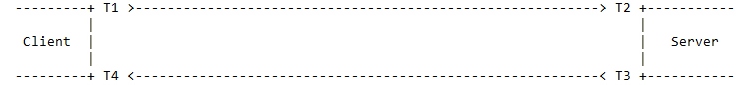
In words, at time T1 (origin) the client sends a UDP/NTP packet to the server with T1 encoded in it. The Server records T2, the receipt time, and T3, the send time, and sends the packet, with T1, T2, and T3 encoded in it, back to the Client, which records T4, the destination time. According to RFC 5905 (Network Time Protocol Specification, Version 4), the offset of the Server relative to the Client is computed by the Client as offset = [(T2 - T1) - (T4 - T3)] / 2 and the round-trip delay as delay = (T4 - T1) - (T3 - T2).
The Client can be communicating with 9 or more servers; an odd number is recommended so a decision can be made. Using a complex algorithm based on the stratum of the server (Primary = 1, Secondary = 2, and pool = 3), the jitter (= the RMS average of the first derivative of the offset), and the magnitude of the of the delay (smaller is better), the Client first separates the servers into true chimers and false tickers, then it chooses the best of the true chimers with which to synchronize its time. Time is synchronized by elongating or shortening the denominated interval between clock ticks on the Client. In other words, the Client slews the clock by adding or subtracting a few parts per million to the nominal time between clock ticks.
There are two problems with this approach: 1. What RFC 5905 actually says is that the offset is supposed to be a maximum likelihood estimator (MLE) of the time offset between the Client and the Server, and the Client's estimate of the true system time is supposed to be a MLE of a linear combination of the various MLEs of the Server offsets. 2. The Client switches between true chimers with which to synchronize its time with some reluctance, and so will stay synchronized with a particular stratum 1 server with a short delay and small jitter for fairly long periods. This means that slight variations in the packet flight times between the Client and the Server will immediately show up as small changes in the offset. In particular, this will occur if one of the routers between the Client and the Server is queuing packets when it becomes busy. One-half the time that the UDP/NTP packet sits in the router's queue will immediately show up as a change in offset by a few hundred microseconds. Since with a broadband connection, time can be synchronized between a client and server within tens of microseconds accuracy, even a few hundreds of microseconds of change in offset is relatively huge.
With regard to the System Modeler, my idea was to simulate the Client and Server(s) using the built-in digital simulation framework. That way I could try several MLE algorithms and debug them. Some of the problems I had were: 1. How do you specify to the digital framework T1, T2, T3, and T4? 2. If S1 = T2 - T1, S2 = T3 - T2, and S3 = T4 - T3, and the Si's have a Normal distribution with a known mean and variance, how to indicate that to the simulation? In other words, for example, T2 = S1 + T1, where S1 is, for simulation purposes, a random Normal deviate with a specified mean and variance. The S1s can be chosen with Mathematica, but how to input them to the System Modeler? 3. Where in the framework does one put computations like offset = [(T2 - T1) - (T4 - T3)] / 2? And, by extension, where and how would one insert an MLE algorithm to compute an MLE of the offset?


