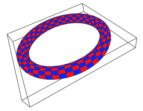
Several years ago, all of a sudden 3D videos became popular. Just last months (year?) 360 degree videos became popular. Facebook and Youtube both have support for 360 degree videos. So it was of course only a matter of time I wanted to try this out. In addition, I will show you how to do it. In order to create such a video, one needs videos that are 'flattened out', which basically means that instead of x and y coordinates we will have ? and ? spherical coordinates (or equivalently longitude and latitude). Here is a snapshot of my trial video; you're inside a torus!
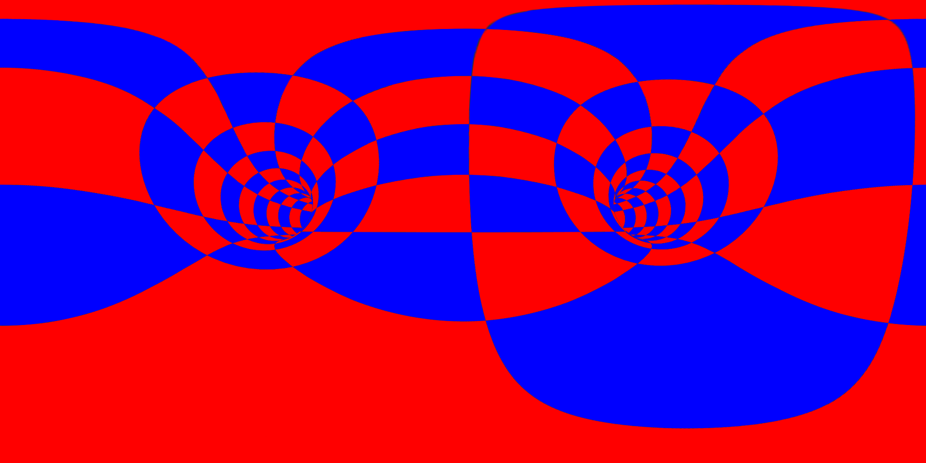
Note the amazing distortion at the top (the top line of pixels is actually a point!) This is caused by 'unwrapping' a sphere, and this is what causes cartographers nightmares, one can not un-wrap a sphere without stretching part of the surface! This is also why Greenland has a similar size to Africa (on Google maps), but in reality it is much smaller. Ok enough about cartography, How did I create such an image?
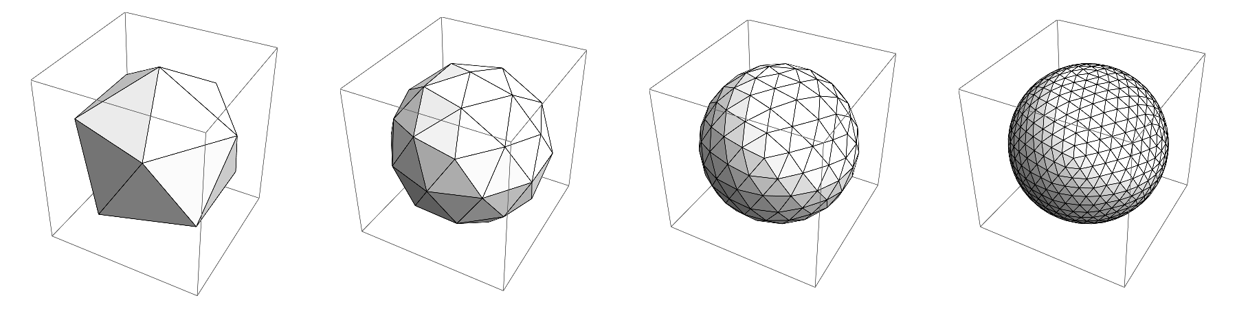
The basic idea is that we have a scene (a torus in this case) and we put our camera at a certain point and take snapshots in the different directions. So Imagine we are inside some polyhedron and look at each of the faces of it and take a snapshot. Depending on how accurate you want to do this you can choose to take 4 very wide snapshots in a tetrahedral configuration, or 6 in a cubic arrangement, 12 in a dodecahedronal arrangement, or 20 in an icosahedronal configuration. I opted for the last option:
ClearAll[RefineSphere]
RefineSphere[{fi_, vc_}] := Module[{vcc, max = Max[fi], nfi, avgs, midpoints, newtriangles, newvc},
vcc = DeleteDuplicates[Sort /@ Flatten[Subsets[#, {2}] & /@ fi, 1]];
nfi = MapThread[Rule, {vcc, max + Range[Length[vcc]]}];
avgs = Mean[vc[[#]]] & /@ vcc;
newvc = Normalize /@ (vc~Join~avgs);
midpoints = Partition[#, 2, 1, 1] & /@ fi;
newtriangles = MapThread[Append[Flatten[#, 1] & /@ ({#2, Partition[Sort /@ RotateRight[#1], 2, 1, 1]}\[Transpose]), Sort /@ #1] &, {midpoints, fi}];
newtriangles = Flatten[Replace[newtriangles, nfi, {3}], 1];
{newtriangles, newvc}
]
refine = 0 (* integer <= 5.... 20*4^refine triangles *)
sphereFI = PolyhedronData["Icosahedron", "FaceIndices"];
sphereVC = N@PolyhedronData["Icosahedron", "VertexCoordinates"];
{sphereFI, sphereVC} = Nest[RefineSphere, {sphereFI, sphereVC}, refine];
sphereVC *= 40;
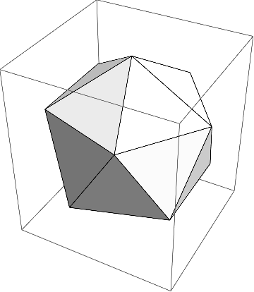
Graphics3D[GraphicsComplex[sphereVC, Polygon[sphereFI]], Lighting -> "Neutral"]
To start, I just used a normal icosahedron, without refining (20 faces):
Now imagine we put the camera at the center of this shape and we look at the centers of each of the triangles. We have to choose an appropriate viewing angle such as to fully see the triangle. After a bit of playing around I found out that a good viewing angle is 80 degrees. Now with that viewing angle we see a certain square-section in 3D, which is determined by two vectors, one going up, and one perpendicular to the vector going up and the viewing-vector:
size = 600;  (* each view will be rendered this size squared *)
vangle = 80 \[Degree]; (* view angle is 80\[Degree] *)

(* calculate the various viewing angles *)

viewvectorup = viewvectors = Normalize[Mean[Part[sphereVC, #]]] & /@ sphereFI;
crosslen = (Norm /@ viewvectors) Tan[vangle/2];
viewvectorup = Normalize[{0, 0, 1} - ({0, 0, 1}.Normalize[#]) Normalize[#]] & /@ viewvectorup;
viewvectorup *= crosslen;
viewvectorright = MapThread[Normalize@*Cross, {viewvectors, viewvectorup}];
viewvectorright *= crosslen;

(* make black-white masks for each view, note that we use 0.96 viewing angle here such that each of the views overlaps a bit *)
masks = MapThread[Rasterize[Graphics3D[{EdgeForm[], White,
       GraphicsComplex[sphereVC, Polygon[#1]]}, Boxed -> False,
      Lighting -> "Neutral", ViewVertical -> {0, 0, 1},
      ViewVector -> {{0, 0, 0}, #2}, ViewAngle -> (0.96 vangle),
      ImageSize -> {size, size}, Background -> None], "Image",
     Background -> None] &, {sphereFI, viewvectors}];

(* this is what all the viewingvectors look like (blue), green is the pointing-up vector, and in red is the vector to the right *)
gr =
 Graphics3D[MapThread[{Blue, Arrow[Tube[{{0, 0, 0}, #1}]], Green,
     Arrow[Tube[{#1, #1 + #2}]], Red,
     Arrow[Tube[{#1, #1 + #3}]]} &, {viewvectors, viewvectorup, viewvectorright}]
]
The red vectors are pointing to the right (from the camera perspective), green pointing up, and blue is the direction of view. As you notice, this is getting quite complicated already... I also calculate the masks that we need later. I will render each of the face, and need the masks for the triangles. I purposely made the masks slightly bigger such that the image of each face overlaps a tiny bit with the adjacent faces.
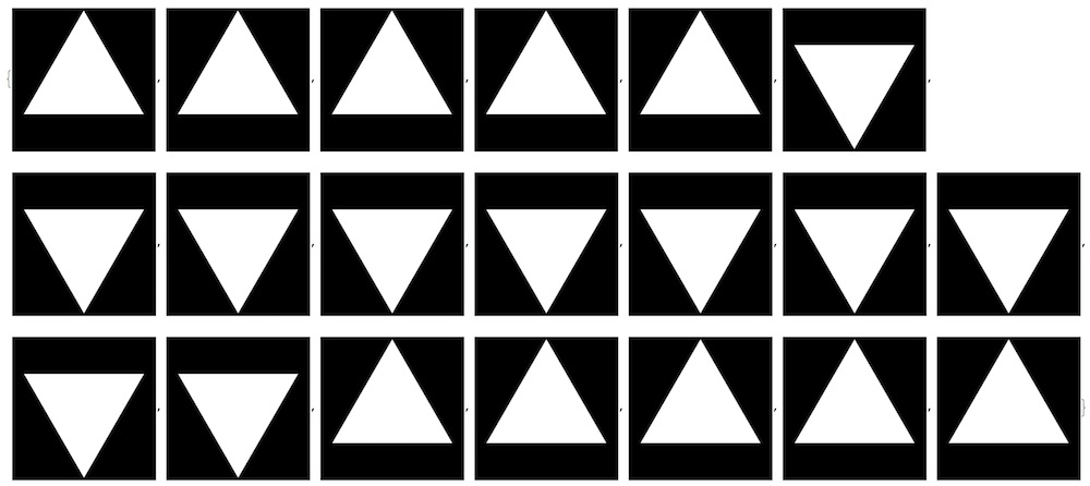
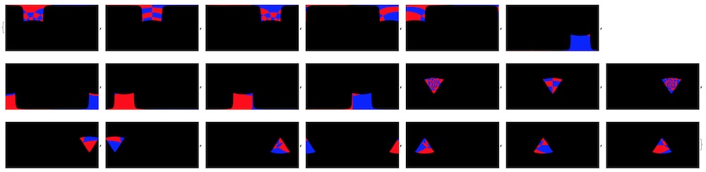
The masks look like this:
RemoveAlphaChannel /@ masks
Now that we have the masks, we need a scene: Here is what I made:
ClearAll[MakeScene]
MakeScene[t_]:=Module[{rot,p1,p2},
    rot=2\[Pi] t;
    p1=ParametricPlot3D[{-8.2+(8+Cos[v]) Sin[u+t],(8+Cos[v]) Cos[u+t],Sin[v]+0.75},{u,0,2Pi},{v,0,2Pi},ViewVector->{{0,0,0},{0,1,0}},ViewAngle->80\[Degree],PlotStyle->Directive[Green,Opacity[1]],MeshShading->{{Red,Blue},{Blue,Red}},MeshFunctions->{#4&,#5&},PlotPoints->80,Axes->False,Mesh->{51,10},Lighting->{{"Ambient",White}},ViewVertical->{0, 0, 1}];
    p2=Graphics3D[{Orange,Sphere[{-8.2-8Sin[2rot],8Cos[2rot],0.45},0.2]},Lighting->{{"Ambient",White}}];
    Show[{p1,p2}]
]
A simple torus that rotates around as a function of time, it looks like something like this:
Now for each of the viewing vectors, we create an image (this is inside the torus!):
views = MapThread[Rasterize[Show[MakeScene[0.0], ViewVector -> {{0, 0, 0}, #1},
 ViewVertical -> {0, 0, 1}, ViewAngle -> vangle, Boxed -> False,
 ImageSize -> {size, size}, Background -> White],
"Image"] &, {viewvectors}]
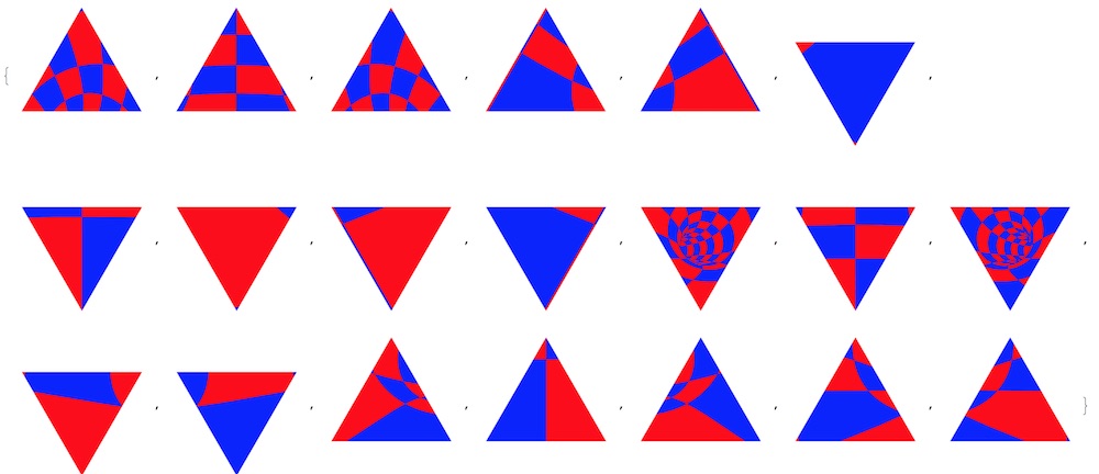
Now we masks each of the views with its corresponding masks to get:
antetransform = MapThread[ImageMultiply, {masks, views}];
Now we have to transform each of the images to ? - ? space, or equally longitude-latitude. There are now 2 ways to do this: One: for each pixel in the above images I calculate the ? and ? coordinates, and then color in that pixel in ?-? space. Or the other way around: For each point in ?-? space i calculate the x-y coordinates of the pixel in the images. Once I transformed all the images to ?-? space I can stack them all up to get my final image. While both can be done, it is in this case easier to go from ?-? space to x-y coordinates in the images. This has to with interpolation when you go the other way; it is confused by the spherical coordinates which are periodic in one direction and data for -179 and 179 degrees will interpolate in between -179 to 179 degrees, rather than wrapping around. (if you don't understand what I'm saying, don't worry, we'll use the other method).
For speed reasons I calculate some normalized vectors and the length of vectors before:
vvv = {viewvectors, viewvectorright, viewvectorup}\[Transpose];
normvvv = Map[Normalize, vvv, {2}];
nvvv = Map[Norm, vvv, {2}];
svv = vvv/nvvv^2;
ClearAll[invtransfunc];
invtransfunc[{\[Phi]_, \[Theta]_}, n_] := Module[{vp},
   vp = {Cos[\[Phi]] Sin[\[Theta]], Sin[\[Theta]] Sin[\[Phi]],
     Cos[\[Theta]]};
   If[vp.vvv[[n, 1]] <= 0,
    vp = (vp nvvv[[n, 1]]/(vp.normvvv[[n, 1]]));
    {vp.svv[[n, 2]], vp.svv[[n, 3]]}
    ,
    {-2, -2}
    ]
   ];
This function converts ?-? coordinates for the nth view vector to x-y coordinates of that image of that view. The if statement is necessary to make sure that if a ?-? pair is requested that is opposite to the camera-view (i.e. behind the camera) that it will not project these angles wrongly. I give it the {-2,2} coordinates in that case, which corresponds to a point outside the image, so it will be transparent.
So we perform now this transformation for each image:
posttransform=Table[ImageTransformation[antetransform[[n]],invtransfunc[#,n]&,DataRange->{{-1,1},{-1,1}},PlotRange->{{-\[Pi],\[Pi]},{0,\[Pi]}},Padding->Transparent],{n,Length[antetransform]}];
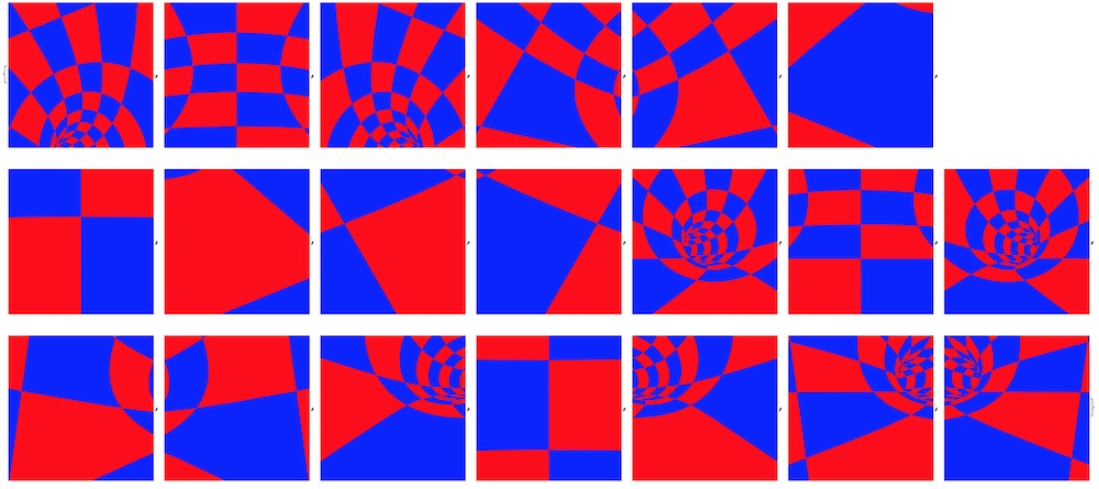
There is lot going on in that simple line, and it take a while to compute:
RemoveAlphaChannel /@ posttransform
Once we have these images, we can combine them using ImageCompose (and some fiddling around with the masks):
\[Alpha]cs = AlphaChannel /@ posttransform;
posttransform = RemoveAlphaChannel /@ posttransform;
\[Alpha]cs = Binarize[#, 0.95] & /@ \[Alpha]cs;
posttransform = MapThread[SetAlphaChannel, {posttransform, \[Alpha]cs}];
imgout = ImageCompose[First[posttransform], Rest[posttransform]];
imgout = RemoveAlphaChannel[imgout];
To finally get this:
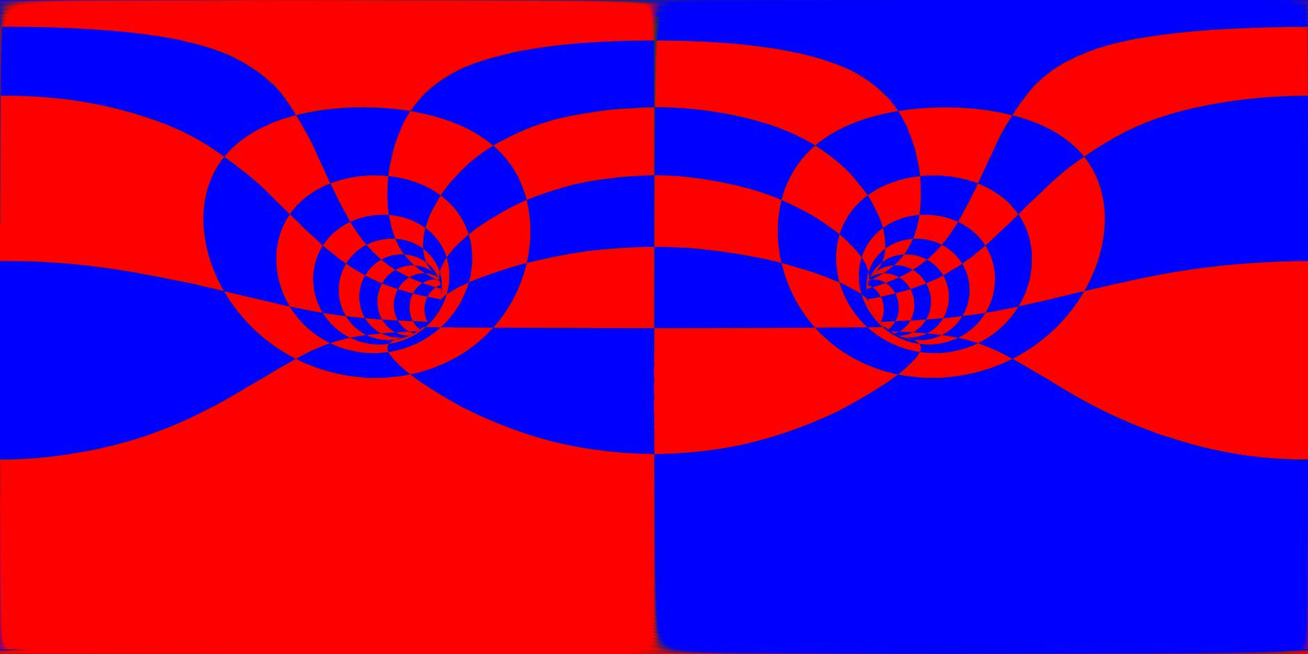
Now if we do that for a bunch of frames and create a movie of this we get this flat video. If we no post this again but with some metadata injected, we can now go through a tunnel and look around in this 360 degree video on YouTube!


