I've been trying out a lot of new ideas lately and doing things I wanted to do before but didn't know how. One such idea was making a map editor for drawing road networks in a graphical environment and having it generate something computable like a graph. With a prototype made, I was then left with some new methods which I felt could be refined by applying to a quick unrelated project.
Here, a GUI allows the user to choose from a selection of logic gates (AND, OR, XOR and their respective negations), place them in a graphical environment and connect them (directly or by drawing wires) to other such gates. The circuit is then rendered into a Boolean expression which is used to generate the circuits output state based on the user's control of the input states. If you've ever used Multisim, Logisim, or something similar then you'll see intended resemblance.
There are limitations and cases where the simulation fails but overall, its a very basic yet effective program which succeeds in it's experimental scope.
Defining the Logic Gate Function
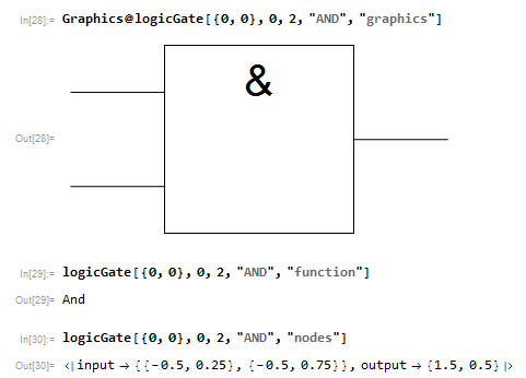
The program uses a single function to handle all instances of the logic gates used. The gate's graphic is drawn from pos={x,y} with a rotation of 0 by default. arity is the number of inputs the gate receives (2,3 and 4 are available) . mode specifies the gate's function (AND,OR.etc) and return specifies the output of logicGate when evaluated ("graphics" for returning the gate's graphic, "nodes" for returning the position of its input/output terminals etc).
I've used the IEEE standard for the graphics as it was much easier to draw and also from personal preference.
logicGate = Function[{pos, rotation, arity, mode, return},
  Which[
   (* draw gate image *)
   return == "graphics",
   Rotate[
    {
     (* frame *)
     {White, EdgeForm[Black], Rectangle[pos]},
     (* symbol - specific to mode *)
     Inset[Style[
       Which[
        mode == "AND" || mode == "NAND", "&",
        mode == "OR" || mode == "NOR", "\[GreaterEqual]1",
        mode == "XOR" || mode == "XNOR", "=1"
        ],
       40], pos + {0.5, 0.8}],
     (* output line *)
     Line[{pos + {1, 0.5}, pos + {1.5, 0.5}}],
     (* negation dot *)
     If[mode == "NAND" || mode == "NOR" || mode == "XNOR",
      {White, EdgeForm[Black], Disk[pos + {1.1, 0.5}, 0.1]}
      ],
     (* input lines *)
     Which[
      arity == 2,
      Table[Line[{pos + {0, i/4}, pos + {-0.5, i/4}}], {i, {1, 3}}],
      arity == 3,
      Table[Line[{pos + {0, i/6}, pos + {-0.5, i/6}}], {i, {1, 3, 5}}],
      arity == 4,
      Table[
       Line[{pos + {0, i/8}, pos + {-0.5, i/8}}], {i, {1, 3, 5, 7}}]
      ]
     }, rotation, pos + {0.5, 0.5}],
   (* give positions of input and output terminals *)
   return == "nodes",
   Which[
    arity == 2,
    <|
     "input" ->
      RotationTransform[rotation, pos + {0.5, 0.5}][
       Table[pos + {-0.5, i/4}, {i, {1, 3}}]],
     "output" ->
      RotationTransform[rotation, pos + {0.5, 0.5}][pos + {1.5, 0.5}]
     |>,
    arity == 3,
    <|
     "input" ->
      RotationTransform[rotation, pos + {0.5, 0.5}][
       Table[pos + {-0.5, i/6}, {i, {1, 3, 5}}]],
     "output" ->
      RotationTransform[rotation, pos + {0.5, 0.5}][pos + {1.5, 0.5}]
     |>,
    arity == 4,
    <|
     "input" ->
      RotationTransform[rotation, pos + {0.5, 0.5}][
       Table[pos + {-0.5, i/8}, {i, {1, 3, 5, 7}}]],
     "output" ->
      RotationTransform[rotation, pos + {0.5, 0.5}][pos + {1.5, 0.5}]
     |>
    ],
   (* gives gates function *)
   return == "function",
   Which[
    mode == "AND",
    And,
    mode == "NAND",
    Nand,
    mode == "OR",
    Or,
    mode == "NOR",
    Nor,
    mode == "XOR",
    Xor,
    mode == "XNOR",
    Xnor
    ]
   ]
  ]
For example, we define a 2 input AND gate drawn from {0,0} and return its graphic, function and location of in/out terminals.
Manipulating the Gate Function
Before attempting to handle an assortment of gates, we need to establish a method for how a single gate can be manipulated. Of interest is how the user can control the states of individual inputs and have the corresponding output correctly displayed.
(* set defaults *)arity = 2; inputState = Table[True, 2];
Panel@Deploy@Column[{
    Row[{
      (* select gate's function *)
      Control@{{mode, "AND",
         Style["Function", 14, "Subtitle"]}, {"AND", "NAND", "OR",
         "NOR", "XOR", "XNOR"}},
      (* select number of inputs *)
      Row[{
        Style["Inputs", 14, "Subtitle"],
        Spacer[3],
        Button[2, arity = 2; inputState = Table[True, 2]],
        Button[3, arity = 3; inputState = Table[True, 3]],
        Button[4, arity = 4; inputState = Table[True, 4]]
        }]
      }, Spacer[5]],
    Dynamic[
     Graphics[{
       (* return gate graphic *)
       logicGate[{0, 0}, 0, arity, mode, "graphics"],
       (* draw input state indicators *)
       Dynamic@Transpose[{
          inputState /. {True -> Green, False -> Red},

          Disk[#, 0.1] & /@
           logicGate[{0, 0}, 0, arity, "AND", "nodes"]["input"]
          }],
       (* insert input state controls *)
       Inset[
          Button["",
           If[inputState[[#]] == True, inputState[[#]] = False,
              inputState[[#]] = True] &[#], ImageSize -> {35, 35},
           Appearance -> "Frameless"],
          logicGate[{0, 0}, 0, arity, "AND", "nodes"][
            "input"][[#]]] & /@ Range[arity],
       (* compute and draw output state indicator*)
       {
        logicGate[{0, 0}, 0, arity, mode, "function"] @@
          inputState /. {True -> Green, False -> Red},
        PointSize[0.05],
        Point[logicGate[{0, 0}, 0, arity, mode, "nodes"]["output"]]}
       }, PlotRange -> {{-1, 2}, {-1, 1.7}}, ImageSize -> Large]
     ]
    }, Alignment -> Center, Spacings -> 2]
The initially constant list inputState is generated with length set by the functions arity and gives the arguments for the gates function. Thus by returning the gates function and applying it to the input list, we get the gates output.
In[25]:= inputState
logicGate[{0, 0}, 0, arity, mode, "function"]
logicGate[{0, 0}, 0, arity, mode, "function"] @@ inputState

Out[25]= {True, True, True, True}

Out[26]= And

Out[27]= True
Replacement via {True->Green,False->Red} to both the input list and the returned output state handles the graphics end.
Dynamic@Transpose[{
   inputState /. {True -> Green, False -> Red},
   Disk[#, 0.1] & /@
    logicGate[{0, 0}, 0, arity, "AND", "nodes"]["input"]
   }]
The user controls the state of each input by clicking on a frameless button which is inserted into the graphic at each of the the locations specified by the gate functions "nodes" option. The ith button acts to replace the ith entry in inputState with either True or False with 1 button per input node.
(* insert input state controls *)
Inset[Button["",
    If[inputState[[#]] == True, inputState[[#]] = False,
       inputState[[#]] = True] &[#], ImageSize -> {35, 35},
    Appearance -> "Frameless"],
   logicGate[{0, 0}, 0, arity, "AND", "nodes"]["input"][[#]]] & /@
 Range[arity]
Generating a Boolean Expression
With a framework for control now established, the next step is to design a method for returning a Boolean expression from the envisioned output of the circuit design GUI. I skipped ahead to this step as I decided it would be easier to get this part done and work backwards. I pictured the eventual output of the GUI to be the edges of a graph which would represent the circuit. Here's an example.
net = Reverse /@ {
    "A" \[DirectedEdge] "F1",
    "B" \[DirectedEdge] "F2",
    "F4" \[DirectedEdge] "F2",
    "C" \[DirectedEdge] "F4",
    "D" \[DirectedEdge] "F4",
    "E" \[DirectedEdge] "F4",
    "F2" \[DirectedEdge] "F3",
    "F1" \[DirectedEdge] "F3",
    "F3" \[DirectedEdge] "X"
    };
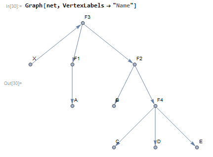
Placeholders "F1","F2",.. represents arbitrary functions, "A","B",.. are the inputs of the expression and "X" is the output. The goal is to get something out which has the form F3[F1[A],F2[B,F4[C,D,E]]]. The placeholders would then be replaced with their corresponding functions and states (i.e., "F1"->Not,"F2"->And,...,"A"->True,"B"->False,..) and thus the expression would return either True or False. Having experimented a bit with gene expression programming and karva notation, I already had an approach in mind but ultimately came up with something much better than my previous attempts.
Using a depth first search on the graph, we begin at "X" and walk until the end (a terminal - or input for the eventual expression) is reached. The search is done for all paths and returns the vertices once they've been visited.
In[54]:= scanList = {};
DepthFirstScan[Graph[net],
  "X", {"PostvisitVertex" -> (AppendTo[scanList, #] &)}];
scanList

Out[56]= {"B", "C", "D", "E", "F4", "F2", "A", "F1", "F3", "X"}
Then the list of vertices is reversed and the starting point ("X") is dropped.
In[57]:= expression = Rest@Reverse@scanList

Out[57]= {"F3", "F1", "A", "F2", "F4", "E", "D", "C", "B"}
Reading left to right, we can see the expression emerge. "F4" is the first function and 'gets' the next 3 elements of the list (it's arity is 3, accessed via its vertex out-degree), hence we want to replace F4,E,D,C in the expression list with F4[E,D,C]. The list is then read up to the next function and the process is repeated until there are no more functions to be read. Thus
In[58]:= scanList = {}; DepthFirstScan[
 Graph[net], "X", {"PostvisitVertex" -> (AppendTo[scanList, #] &)}];
expression = Rest@Reverse@scanList;
functionArity = AssociationThread[
   VertexList[net] ->
    VertexOutDegree[net]
   ];
functionList = Select[Keys[functionArity], StringContainsQ[#, "F"] &];
While[functionList != {},
  i = 1; While[ContainsAny[functionList, {expression[[-i]]}] == False,
    i++];
  functionList =
   Delete[functionList, Position[functionList, expression[[-i]]][[1]]];
  expression =
   Append[Drop[
     expression, {(-i), (-i) + functionArity[expression[[-i]]]}],
    expression[[-i]] @@
     expression[[(-i) + 1 ;; (-i) + functionArity[expression[[-i]]]]]]
  ];

x = expression[[1]]

Out[63]= "F3"["F2"["B", "F4"["E", "D", "C"]], "F1"["A"]]
Now we replace the function placeholders to get a Boolean expression
In[43]:= x /. {
  "F1" -> Not,
  "F2" -> And,
  "F3" -> Or,
  "F4" -> Nand
  }

Out[43]= ("B" && ("E" \[Nand] "D" \[Nand] "C")) || ! "A"
To evaluate the expression, we replace the terminal placeholders with their desired states
In[44]:= ("B" && ("E" \[Nand] "D" \[Nand] "C")) || ! "A" /. {
  "A" -> True,
  "B" -> True,
  "C" -> True,
  "D" -> True,
  "E" -> True
  }

Out[44]= False
Now need a GUI which allows the user to draw circuits and generates an output compatible with this method.
Drawing a Logic Circuit
The first step is to be able to place logic gates into position and store them in memory. LocatorPane is used to relay the mouse position into the function logicGate which is set to return a graphic.
Framed@Dynamic[
   EventHandler[
   LocatorPane[
    Dynamic[pt],
    Dynamic[
     (* circuit draw interface *)
     Graphics[{
       Which[
        (* preview active gate in case of mode *)
        inputMode == "placeGate",
        logicGate[pt, \[Theta], arity, mode, "graphics"],

        (* preview wire *)
        inputMode == "drawWire",
        If[Length[wirePoints] > 0,
         {
          Line[Append[wirePoints, pt]],
          {PointSize[0.01], Point[wirePoints[[1]]]}
          }
         ]
        ],
       (* view drawn circuit *)
       circuitGraphic,
       (* plot connections *)
       If[Values[Join @@ Values[circuitData[[All, "input"]]]] != {},
        {PointSize[0.01],
         Point[Intersection[
           Values[Join @@ Values[circuitData[[All, "input"]]]],
           Values[Join @@ Values[circuitData[[All, "output"]]]]]]}
        ]
       },
      PlotRange -> {{0, 8}, {0, 8}},
      ImageSize -> Large
      ]
     ],
    Appearance -> None
    ],
   {"MouseUp" :> Which[
      inputMode == "placeGate", snapToProximalNode,
      inputMode == "drawWire",
      Which[
       Length[wirePoints] == 0 && wireSnapTo =!= Null,
       AppendTo[wirePoints, wireSnapTo],
       Length[wirePoints] > 0 && wireSnapTo == Null &&
        wireSnapToTerminate == Null,
       AppendTo[wirePoints, pt],
       Length[wirePoints] > 0 && wireSnapTo == Null &&
        wireSnapToTerminate =!= Null,
       AppendTo[wirePoints, wireSnapToTerminate]
       ]
      ], PassEventsDown -> True
    }
   ]
  ]
Once placed, a button is used to 'set' the gate into the program. The buttons behaviour changes depending on the GUIs 'mode' (either placing gates or drawing wires) but each has a similar process: append graphics to a list, append data to a list. For the case of a gate, the graphic object returned via logicGate[pt, \[Theta], arity, mode, "graphics"] is appended to the list circuitGraphic initialised as {}.
AppendTo[circuitGraphic, logicGate[pt, \[Theta], arity, mode, "graphics"]]
To generate any useful output however, the locations of the gates nodes and its function must also be recorded. An association is used for easy retrieval and organisation since nodes will need to be identified to not only their respective gate but also if they represent an input or output.
Clicking on the 'Set' button generates an association of the gate (1,2,3..) to its function and input & output nodes. The nodes are indexed sequentially and categorised separately.
AppendTo[circuitData,
 Length[circuitData] + 1 -> <|
   "function" -> logicGate[pt, \[Theta], arity, mode, "function"],
   "input" -> AssociationThread[
     If[
       Length[circuitData] == 0,
       (Rest@Range[0, arity] + Length[circuitData]),
       Most@
        Range[(Keys[(Last@circuitData)["output"]] + 1)[[
          1]], (Keys[(Last@circuitData)["output"]] + 1)[[1]] + arity]]
      -> logicGate[pt, \[Theta], arity, mode, "nodes"]["input"]],
   "output" -> <|
     If[
       Length[circuitData] == 0 ,
       Last[(Rest@Range[0, arity] + Length[circuitData])] + 1,
       Last[Most@
          Range[(Keys[(Last@circuitData)["output"]] + 1)[[
            1]], (Keys[(Last@circuitData)["output"]] + 1)[[1]] +
            arity]] + 1
       ]
      -> logicGate[pt, \[Theta], arity, mode, "nodes"]["output"]|>
   |>
 ]


In[78]:= circuitData

Out[78]= <|
1 -> <|
"function" -> And, "input" -> <|1 -> {1.22, 5.91}, 2 -> {1.22, 6.41}|>, "output" -> <|3 -> {3.22, 6.16}|>
|>,
 2 -> <|
"function" -> And,  "input" -> <|4 -> {1.47, 3.62}, 5 -> {1.47, 4.12}|>, "output" -> <|6 -> {3.47, 3.87}|>
|>,
 3 -> <|
"function" -> And, "input" -> <|7 -> {5.22, 5.57}, 8 -> {5.22, 6.07}|>, "output" -> <|9 -> {7.22, 5.82}|>
|>,
 4 -> <|
"function" -> And, "input" -> <|10 -> {3.415, 1.5}, 11 -> {3.415, 2.}|>, "output" -> <|12 -> {5.415, 1.75}|>
|>
|>
Gates which are connected to each other will be identified by looking for node positions from two different gates but with the exact same value. (These values are used as the locations for the points drawn when a connection between terminals/wires is made). Its unreasonable to need the user to place gates with so much precision as for them to appear connected so the GUI detects any instance of nodes from the active gate (the one the user is in the process of placing) coming into proximity with nodes from already placed gates and 'snaps' the active gate into place. I considered using a more traditional grid interface but decided that a freeform placement method offered greater flexibility and interest.
snapToProximalNode :=
 If[Values[Join @@ Values[circuitData[[All, "input"]]]] != {},
  With[{

(* these are the nodes belonging to gates already placed *)
    placedNodes = Join[
      Values[Join @@ Values[circuitData[[All, "input"]]]],
      Values[Join @@ Values[circuitData[[All, "output"]]]]
      ],

(* these are the nodes of the active gate *)
    activeNodes = Join[
      logicGate[pt, \[Theta], arity, mode, "nodes"]["input"],
      {logicGate[pt, \[Theta], arity, mode, "nodes"]["output"]}
      ]
    },
   Block[{i},
    i = 1;
    While[
(* for each active node, beginning with the first in list, search for a placed node that is within a radius of 0.2. *)
     Nearest[placedNodes, activeNodes[[i]], {1, 0.2}] == {} && i <= Length[activeNodes],
(* If none found, go on to next active node *)
     If[i < Length[activeNodes], i++, i = 0; Break[]]];
(* if a proximal node is found, calculate the difference in position between active gate origin (pt) and proximal node *)
    If[i != 0,
(* adjust active gate position so that proximal nodes now lie on top of each other *)
     pt +=
      Nearest[placedNodes, activeNodes[[i]], {1, 0.2}][[1]] -
       activeNodes[[i]]
     ]
    ]
   ]
  ]
So that snapToProximalNode is evaluated automatically, the locator pane based interface is wrapped in an event handler which performs gate (and wire) snapping whenever the mouse button is released.
Drawing wires includes similar routines for snapping the end of a wire to any nearby gate. Wires may only be drawn form an existing terminal but are allowed to end anywhere. In a computational sense, when the user draws a wire, they are actually getting the location of the node that the wire begins at and changes its value to the position of the wires end point, i.e., a simple extension of the gates terminal. The same instance of event handler mentioned earlier also appends the mouse location to a temporary list for drawing the wire before being appended to the graphics list.
With the GUI tools set up, the next step is to have it assemble the info from circuitData into a series of connected nodes. Two things must be done: 1- find and connect output nodes which are joined to input nodes of other gates 2 - connect a gates output nodes to its input nodes for all gates.
For step 1, all output nodes, beginning with the first in circuitData are compared for equality against input nodes - if there's a match, their IDs (indices from circuitData) form the basis of a directed edge. When repeated, we would get something like F1->a->F2->b... but what is actually being represented is more like F1->F2->.. i.e., we need to represent the connected gate by its output and not by its connected input.
We take a similar approach with step 2 where when connecting corresponding inputs and outputs for each gate, we ignore making connections between inputs which are already connected to another gate.
This will generate a list of connected vertices
In[101]:= Module[{
  outputNodeID = Join @@ Values[circuitData[[All, "output"]]],
  inputNodeID = Join @@ Values[circuitData[[All, "input"]]]
  },
 connections = {};
 connections = Block[{
    i = 1, j = 1
    },
   (* connecting out nodes to in nodes for different gates *)
   Do[
    While[(outputNodeID[Keys[outputNodeID][[i]]] ==
        inputNodeID[Keys[inputNodeID][[j]]]) == False,
     If[j < Length[Keys[inputNodeID]], j++, j = 0; Break[]]];
    If[j != 0,
     AppendTo[connections,
      (* get outnode belonging to in node of connecetd gate *)
      Keys[outputNodeID][[i]] \[DirectedEdge] Block[{k = 1},
        While[
         ContainsAny[
           Keys[circuitData[k]["input"]], {Keys[inputNodeID][[j]]}] ==
           False, k++
         ];
        Keys[circuitData[k]["output"]][[1]]
        ]
      ]
     ];
    j = 1,
    {i, 1, Length[Keys[outputNodeID]]}
    ];
   (* connect output nodes to input nodes for same gates except if \
input already connected to another gate's out node*)
   Do[
    AppendTo[connections,
     DirectedEdge @@@ Transpose[{
          #,
          Table[Keys[circuitData[i]["output"]][[1]], Length[#]]
          }] &[
      Extract[Keys[circuitData[i]["input"]],
       Position[
        ContainsAny[Values[outputNodeID], {#}] & /@
         Lookup[inputNodeID, Keys[circuitData[i]["input"]]], False]]]
     ],
    {i, 1, Length[circuitData]}
    ];
   Flatten[connections]
   ]
 ]

We identify the vertex representing the output of the circuit by its out-degree; it will be 0. Joined to it is a new vertex representing the output state of the function.
In[103]:= (* add function terminal *)
AppendTo[connections,
 (Extract[VertexList[#], Position[VertexInDegree[#], 0]] &[
     Graph[Reverse /@ connections]])[[1]] \[DirectedEdge] "f1"]

For the vertices representing functions, we replace them with function placeholders
In[105]:= (* sub in function placeholders *)
connections = (Reverse /@ connections) /.
  Normal[AssociationThread[
    Keys[outputNodeID] ->
     Table["F" <> ToString[i], {i, 1, Length[Keys[outputNodeID]]}]]]

And similarly for those representing inputs
In[106]:= (* sub in input placeholders *)
connections =
 connections /.
    Thread[# -> ToUpperCase /@ Alphabet[][[1 ;; Length[#]]]] &[
  Extract[VertexList[Graph[connections]],
   Position[VertexOutDegree[Graph[connections]], 0]]]

A list of replacement rules is made for later
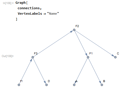
In[107]:= (* generate evaluation replacement rules *)
functionReplaceRules =
 Thread[Table[
    "F" <> ToString[i], {i, 1, Length[Keys[outputNodeID]]}] ->
   Values[circuitData[[All, "function"]]]]

Out[107]= {"F1" -> And, "F2" -> And, "F3" -> And}
connections now forms a graph which fulfils the requirements set out earlier and so may be parsed into a Boolean expression.
The method of controlling the gate function set earlier is extended to multiple gates and a similar interface for control is added.
Conclusion
While some pretty big limitations exist (user can't join multiple outputs to same input) and by the end of the project I had still never bothered to include a basic NOT gate, these issues are second to the projects success as an experiment in new methods and a chance to refine existing ones in a different setting.
 Attachments:


