Looking at the YouTube illusion "Ambiguous Garage Roof" by the Kokichi Sugihara demonstrates once more that what we see does not always represent reality. His beautiful illusion is based on perspective anamorphism. This kind of anamorphic effect shows a completely deformed image and only needs a specific viewpoint to see the undeformed picture. It would be hard to equal the perfection of Mr. Sugihara but we can explore this type of anamorphic illusions with Mathematica...
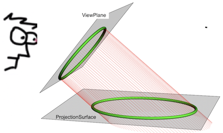
Above is a deformed tubular curve observed by the eye as a circular one. The eye tends to put the observed image in a plane perpendicular to the view direction: the "view plane". We take the view plane as parallel with the y-axis and forming the viewing angle phi with the z-axis.
viewPlane = InfinitePlane[{0, 0, 0}, {{0, 1, 0}, {1, 0, Cot[phi]}}];
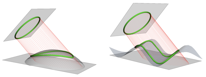
The "projection surface", where the deformed image is located, can be any surface flat or curved. Here are two examples: a sphere (L) and a sinusoidal surface (R). In both cases, the deformed (perspective anamorphic) image is very different but the same circle is seen by the observer if he has the right viewing angle.
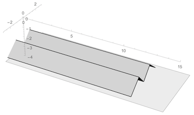
The projection surface we will use here is a folded set of rectangles parallel to the x-axis:
projProfile = {{-2.5, -3.9}, {-1.05, -2.8}, {0, -3.9}, {1.05, -2.8}, \
{2.5, -3.9}};
projectSurface =
  RegionUnion[
   Rationalize[
    Polygon /@
     Map[Flatten[#, 1] &,
      Transpose[{Partition[Prepend[#, -10] & /@ projProfile, 2, 1],
        Reverse /@
         Partition[Prepend[#, 10] & /@ projProfile, 2, 1]}]]]];
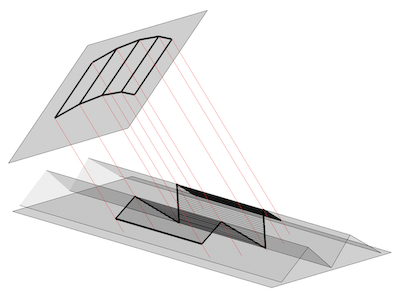
The observed image consists of image points. Rays, straight lines perpendicular to the view plane, are leaving the image points and will intersect the projection surface to form the anamorphic image. This is a function that computes these intersections:
intersect[pt_List] :=
 Quiet[First[{x, y, z} /.
    NSolve[Element[{x, y, z}, HalfLine[pt, {1, 0, -Tan[phi]}]] &&
      Element[{x, y, z}, projectSurface], {x, y, z}]]]
To start with our function, we compute the anamorphic image of a circle in the view plane:
phi = Pi/4;
circle = Table[
   Prepend[AngleVector[{0, 2}, {2, t}], 0], {t, 0, 2 Pi, Pi/20}];
virtCircle = RotationTransform[phi, {0, 1, 0}][circle];
rays = HalfLine[#, {1, 0, -Tan[phi]}] & /@ virtCircle;
anaCircle = intersect /@ virtCircle;
Graphics3D[{{Opacity[.35],
   InfinitePlane[{0, 0, -4}, {{0, 1, 0}, {1, 0, 0}}]}, {Opacity[.25],
   viewPlane, projectSurface[[-1]]}, {Green, Tube[virtCircle, .1],
   Tube[anaCircle, .1]}, {AbsoluteThickness[.5], Red, Thin, rays}}]
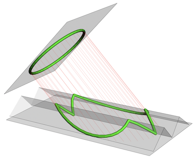
The perspective anamorphic image is a curve in the projection plane. It takes different shapes as we change our viewing angle. These shapes range from the original circle over the anamorphic image to the projection surface profile. The observer sees the original circle only if the viewing angle is phi.
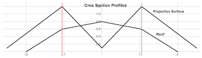
We now look at the garage roof cross section profile. This consists of line segments defined by a list of point coordinates. We chose a roof profile with sections aligned to the projection surface profile:
roofProfile = {{0, -2, 0}, {0, -1.05`, 0.6}, {0, 0, 1}, {0, 1.05,
    0.8}, {0, 2, 0}};
ListLinePlot[{projProfile, Rest /@ roofProfile}]
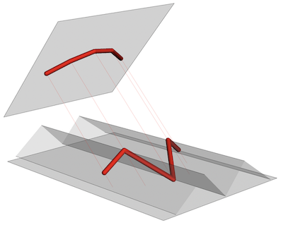
This is the roof profile and its anamorphic image on the projection surface:
We are now ready to test the complete garage roof as a set of 4 rectangles between roof profiles at the front and back:
roofBack = roofProfile /. {x_, y_, z_} -> {x, y, z + 4 Cos[phi]};
roofLines =
  Transpose[{roofProfile,
    roofProfile /. {x_, y_, z_} -> {x + 4, y, z}}];
virtlRoofs =
  RotationTransform[phi, {0, 1, 0}] /@ {roofBack, roofProfile};
anaRoofs = Map[intersect, virtlRoofs, {2}];
Graphics3D[{AbsoluteThickness[3],
  Map[Line, {roofProfile,
    TranslationTransform[{4, 0, 0}] /@ roofProfile, roofLines}]},
 Boxed -> False]
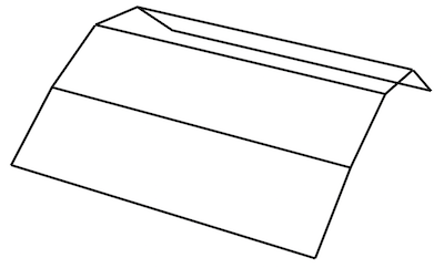
Here is the perceived roof in the view plane and its anamorphic image in the projection surface.
Graphics3D[{{Opacity[.35],
   InfinitePlane[{0, 0, -4}, {{0, 1, 0}, {1, 0, 0}}]}, {Opacity[.25],
   viewPlane, Opacity[.15], projectSurface[[-1]]}, {Gray,
   Tube[virtlRoofs, .03], Tube[Transpose[virtlRoofs], .03]}, {Gray,
   Tube /@ anaRoofs, Tube /@ Transpose[anaRoofs]}, {Red,
   Map[HalfLine[#, {1, 0, -Tan[phi]}] &, virtlRoofs, {2}]}}]
This GIF shows a sequence of different viewing directions of the complete garage with its anamorphic roof:
Module[{pts1},
  pts1 = RotationTransform[\[Phi], {0, 0, 1}] /@
    Join[Flatten[{anaRoof2, anaRoof1},
      1], {{3.52, -2., -3.9 - 1}, {7.52, -2., -3.9 - 1}, {3.52,
       2., -3.9 - 1}, {7.52, 2., -3.9 - 1}}];
  frames =
   ParallelTable[
    Graphics3D[{FaceForm[LightGray], EdgeForm[Thick],
      ph = Polyhedron[
        pts1, {{1, 2, 7, 6}, {1, 2, 7, 6} + 1, {1, 2, 7, 6} +
          2, {1, 2, 7, 6} + 3, {1, 6, 12, 11}, {5, 10, 14, 13}, {11,
          12, 14, 13}}]}, Lighting -> "Neutral", Boxed -> False,
     ViewPoint ->
      20 {-Cos[\[Phi]], Sin[\[Phi]], Tan[\[Pi]/4]}], {\[Phi], \[Pi]/4,
      0, -\[Pi]/160}];
  Export[NotebookDirectory[] <> "garage views.GIF", frames,
   AnimationRepetitions -> \[Infinity]]];
Since the projection surface used is a developable surface, we can build the anamorphic garage and its roof out of cardboard paper . This code computes the 2D development of the anamorphic roof...
development[d_, d1_, d2_, d3_, d4_, d5_, z0_ : 40, d0_ : 2.5] :=
 Module[{projProfile, devlOrdinates, anchors},
  projProfile = {{-d0, d1 - z0}, {-d, d2 - z0}, {0, d3 - z0}, {d,
     d4 - z0}, {d0, d5 - z0}};
  devlOrdinates =
   Prepend[Accumulate@
     Apply[EuclideanDistance, Partition[projProfile, 2, 1], {1}], 0];
  Interpolation[Transpose@{projProfile[[All, 1]], devlOrdinates},
   InterpolationOrder -> 1]]
With[{d1 = 0.1`, d2 = 1.2, d3 = 0.1, d4 = 1.2, d5 = 0.1, d = 1.05},
 projProfile = {{-2.5, -3.9}, {-1.05, -2.8}, {0, -3.9}, {1.05, -2.8}, \
{2.5, -3.9}};
 roofProfile = {{0, -2, 0}, {0, -1.05`, 0.6}, {0, 0, 1}, {0, 1.05,
    0.8}, {0, 2, 0}};
 anaOrdinates1 =
  development[d, d1, d2, d3, d4, d5] /@ roofBack[[All, 2]];
 anaOrdinates2 =
  development[d, d1, d2, d3, d4, d5] /@ roofProfile[[All, 2]];
 devVertices1 = Transpose@{anaRoof1[[All, 1]], anaOrdinates1};
 devVertices2 = Transpose@{anaRoof2[[All, 1]], anaOrdinates2};]
Graphics[{{AbsoluteThickness[3],
   Line /@ Transpose[{devVertices1,
      devVertices2}]}, {AbsoluteThickness[2], Line[devVertices1],
   Line[devVertices2]}}]
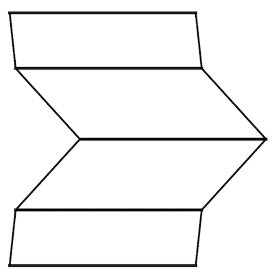
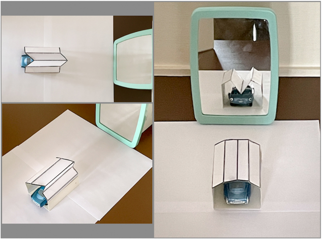
... and we can use it tomake a complete garage from it.
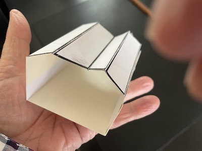
This collage shows the garage from different view angles. Only a viewing angle from 45 degrees with view plane parallel to the y axis will give he desired, "realistic", view.