Message Boards Message Boards

1
|
8398 Views
|
4 Replies
|
5 Total Likes
View groups...
Share
Share this post:

How to get the perimeter of an image structure correctly?

Dear all,

I would need the perimeter of structures in images very precisely. So I started by doing some simple test:

enter image description here

Here is the above code:

img = ColorNegate@ColorConvert[Image@Graphics[Disk[]], "Grayscale"]
ImageDimensions[img]
ComponentMeasurements[img, #] & /@ {"Length", "Width"}
diameter = (1 /. ComponentMeasurements[img, "PolygonalLength"])/Pi

While "Length" and "Width" do make sense with reference to ImageDimensions the calculated diameter (by using the perimeter) is just wrong! Or am I making a stupid mistake?

Many thanks and best regards -- Henrik

POSTED BY: Henrik Schachner
4 Replies

Interesting. It looks like the radius computed from the polygon perimeter is the Authalic Radius, which is counting the length of the sides of the pixels that form the boundary.

In[89]:= (1 /. ComponentMeasurements[img, "AuthalicRadius"])*2

Out[89]= 363.41

If you compute the diameter instead based on the ConvexPerimeterLength, it gets a bit closer to the measurements given by the Length and Width properties that describe the best-fit ellipse. The points along the convex hull don't hug the pixel elements closely and look a bit closer to what you'd expect of a circle-like polygon around the component.

In[88]:= (1 /. ComponentMeasurements[img, "ConvexPerimeterLength"])/Pi

Out[88]= 346.648

You can see the difference between the polygon perimeter and the convex perimeter if you use a smaller circle and plot the points along the boundary. In the example here, the blue points are the perimeter positions of the boundary pixels, while the orange points are the vertices of the convex hull.

img = ColorNegate@ColorConvert[Image@Graphics[Disk[], ImageSize -> {50, 50}], "Grayscale"];
ListLinePlot[{(1 /. ComponentMeasurements[img, "PerimeterPositions"])[[1]], 
              (1 /. ComponentMeasurements[img, "ConvexVertices"])}, 
             PlotRange -> All, Joined -> False]

Boundary points

Interestingly, computing the area and deriving the diameter from that gets closest to the ellipse parameters computed by Length and Width.

In[15]:= Sqrt[(1 /. ComponentMeasurements[img, "Area"])/Pi]*2

Out[15]= 345.658

In[13]:= ComponentMeasurements[img, #] & /@ {"Length", "Width"}

Out[13]= {{1 -> 345.63}, {1 -> 345.502}}

Unfortunately, the convex perimeter isn't going to help you if you are looking to calculate the perimeter of a non-convex object in the image. You might be stuck with the PerimeterLength measurement for those kinds of shapes.

POSTED BY: Matthew Sottile

Hi Matthew,

thank you for looking into this problem! I found it interesting that "ConvexPerimeterLength" is giving a much better value. But as you pointed out this does not work for general objects.

I was rather hoping that maybe I was misunderstanding the term "PolygonalLength" or some other stupid thing. But as it seems ComponentMeasurements[_, "PolygonalLength"] is giving a wrong value. But what is worse: One looses the faith in those functions. Am I supposed to make plausibility tests before I use them?

Meanwhile I found a workaround:

ArcLength[RegionBoundary[ImageMesh[img]]]/Pi
(*  Out:    344.696  *)

Best regards -- Henrik

POSTED BY: Henrik Schachner

Don't loose faith, report bugs and read the documentation carefully! =)

"PolygonalLength" is described as the

total length of the polygon formed by the centers of the perimeter elements

and indeed if you get the perimeter pixel positions and compute the length you get exactly the same value (I am disabling the antialiasing to make things easier)

img = ColorConvert[Rasterize[
   Graphics[{White, Style[Disk[], Antialiasing -> False]}, 
    Background -> Black]],
  "Grayscale"];
perimeterPixels = ComponentMeasurements[img, "PerimeterPositions"][[1, 2, 1]]; 
ArcLength[Line[Append[perimeterPixels, First[perimeterPixels]]]]
(* ==> 1140.03 *)

ComponentMeasurements[img, "PolygonalLength"][[1, 2]]
(* ==> 1140.03 *)

The issue here is that you are approximating a circle with a series of lines that is strictly longer. You can see it well by comparing the different approximation methods in ImageMesh:

ArcLength@RegionBoundary@ImageMesh[img, Method -> #] & /@ {"Exact", 
  "LinearSeparable", "MarchingSquares", "DualMarchingSquares"}
(* ==> {1376., 1085.78, 1142.86, 1112.12} *)

The first value is exactly the length of the outer contour

ArcLength[ComponentMeasurements[img, "Contours"][[1, 2, 1]]]
(* ==> 1376 *)

The solution to your problem really depends on what precise means in your context. If you want to approximate the underline ideal circle one way could be to average the pixel center positions

ArcLength[
 Line@MovingAverage[Append[perimeterPixels, First[perimeterPixels]], 
   2]]
(* ==> 1095.44 *)

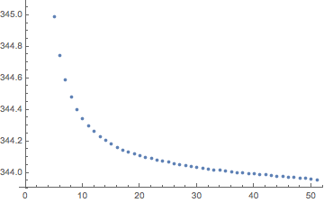
Iterating on the procedure you get a convergence of sort:

dual[list_] := MovingAverage[Append[list, First[list]], 2]
ArcLength@*Line /@ NestList[dual, perimeterPixels, 50]/Pi // ListPlot

perimeter_length

Hi Giulio,

many thanks for your detailed clarification! In this case I definitely prefer to see that the mistake is on my side - otherwise it would have been too stupid! I do read the documentation carefully, but I envisioned that a "polygon formed by the centers of the perimeter elements" would be something like a smooth curve or at least some approximation - in contrast to "PerimeterLength" as "total length of outer pixel sides". And on my machine here (v. 11.1.1) there is no ComponentMeasurements[_, "PerimeterPositions"], which would have helped.

Again many thanks and best regards -- Henrik

POSTED BY: Henrik Schachner
Reply to this discussion
Community posts can be styled and formatted using the Markdown syntax.
Reply Preview
Attachments
Remove
or Discard

Group Abstract Group Abstract