Don't loose faith, report bugs and read the documentation carefully! =)
"PolygonalLength" is described as the
total length of the polygon formed by the centers of the perimeter elements
and indeed if you get the perimeter pixel positions and compute the length you get exactly the same value (I am disabling the antialiasing to make things easier)
img = ColorConvert[Rasterize[
   Graphics[{White, Style[Disk[], Antialiasing -> False]},
    Background -> Black]],
  "Grayscale"];
perimeterPixels = ComponentMeasurements[img, "PerimeterPositions"][[1, 2, 1]];
ArcLength[Line[Append[perimeterPixels, First[perimeterPixels]]]]
(* ==> 1140.03 *)

ComponentMeasurements[img, "PolygonalLength"][[1, 2]]
(* ==> 1140.03 *)
The issue here is that you are approximating a circle with a series of lines that is strictly longer. You can see it well by comparing the different approximation methods in ImageMesh:
ArcLength@RegionBoundary@ImageMesh[img, Method -> #] & /@ {"Exact",
  "LinearSeparable", "MarchingSquares", "DualMarchingSquares"}
(* ==> {1376., 1085.78, 1142.86, 1112.12} *)
The first value is exactly the length of the outer contour
ArcLength[ComponentMeasurements[img, "Contours"][[1, 2, 1]]]
(* ==> 1376 *)
The solution to your problem really depends on what precise means in your context.
If you want to approximate the underline ideal circle one way could be to average the pixel center positions
ArcLength[
 Line@MovingAverage[Append[perimeterPixels, First[perimeterPixels]],
   2]]
(* ==> 1095.44 *)
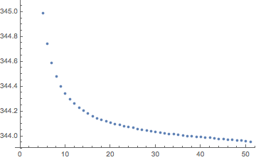
Iterating on the procedure you get a convergence of sort:
dual[list_] := MovingAverage[Append[list, First[list]], 2]
ArcLength@*Line /@ NestList[dual, perimeterPixels, 50]/Pi // ListPlot
