Message Boards Message Boards

0
|
4775 Views
|
1 Reply
|
0 Total Likes
View groups...
Share
Share this post:

Plot Labels with arrows or lines pointing to different curves?

Posted 5 years ago

I'm trying to get plot labels with arrows or lines pointing to different curves. If I do

A2 = 1;
Plot[Evaluate@
  Table[Labeled[Sqrt[x^2 - x^4]/Sqrt[
    1 + A2 \[Beta]], \[Beta]], {\[Beta], {.1, .5, 1, 5, 10, 20}}], {x,
   0, 1.2}, AxesLabel -> {Subscript[k, x], Subscript[k, y]}, 
 PlotRange -> All, LabelStyle -> Directive[14, Bold]]

I get the following image.

Dispersion relations

How do I make the lines point to a better part of the curves?

I've also tried something along the lines of

Plot[Evaluate@
  Table[Sqrt[x^2 - x^4]/Sqrt[
   1 + \[Beta]], {\[Beta], {.1, .5, 1, 5, 10, 20}}], {x, 0, 1.2}, 
 PlotLabels -> 
  Placed[{"\[Beta] = .1", "\[Beta] = .5", "\[Beta] = 1", 
    "\[Beta] = 5", "\[Beta] = 10", "\[Beta] = 20"}, Above], 
 PlotRange -> All]

I've tried using Scaled[] as well. Those options seem to move the labels around but remove the lines pointing to the curves.

POSTED BY: Derek Handwerk

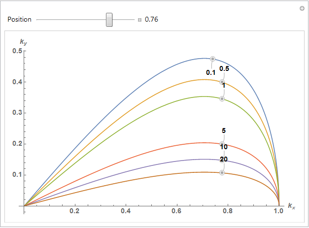
You may want to try experimenting with Callout[].

A2 = 1;
Manipulate[
 Plot[Evaluate@
   Table[Callout[Sqrt[x^2 - x^4]/Sqrt[1 + A2 \[Beta]], \[Beta], pos, 
     CalloutMarker -> "CirclePoint"], {\[Beta], {.1, .5, 1, 5, 10, 
      20}}], {x, 0, 1.2}, 
  AxesLabel -> {Subscript[k, x], Subscript[k, y]}, PlotRange -> All, 
  LabelStyle -> Directive[14, Bold], 
  ImageSize -> Large], {{pos, 0.8, "Position"}, 0, 1, 
  Appearance -> "Labeled"}]

Callout Example

Update

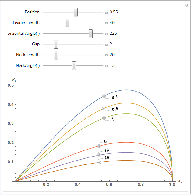
The LeaderSize option will give you more control over the callout placement. You can experiment with the manipulate below. For me, the largest effects were adjusting the Neck parameters.

A2 = 1;
m = Manipulate[
  Plot[Evaluate@
    Table[Callout[Sqrt[x^2 - x^4]/Sqrt[1 + A2 \[Beta]], \[Beta], pos, 
      Background -> White, 
      LeaderSize -> {{leadlen, horizangle Degree, gap}, {neck, 
         neckangle Degree}}, 
      CalloutMarker -> "CirclePoint"], {\[Beta], {.1, .5, 1, 5, 10, 
       20}}], {x, 0, 1.2}, 
   AxesLabel -> {Subscript[k, x], Subscript[k, y]}, PlotRange -> All, 
   LabelStyle -> Directive[14, Bold], 
   ImageSize -> Large], {{pos, 1/Sqrt[2], "Position"}, 0, 1, 
   Appearance -> "Labeled"}, {{leadlen, 40, "Leader Length"}, 0, 100, 
   Appearance -> "Labeled"}, {{horizangle, 225, 
    "Horizontal Angle(\[Degree])"}, -360, 360, 
   Appearance -> "Labeled"}, {{gap, 2, "Gap"}, 0, 10, 
   Appearance -> "Labeled"}, {{neck, 20, "Neck Length"}, 0, 100, 
   Appearance -> "Labeled"}, {{neckangle, 20, 
    "NeckAngle(\[Degree])"}, -360, 360, Appearance -> "Labeled"}]

enter image description here

POSTED BY: Tim Laska
Reply to this discussion
Community posts can be styled and formatted using the Markdown syntax.
Reply Preview
Attachments
Remove
or Discard

Group Abstract Group Abstract