This post shows how to use the GPIO with the Wolfram Language on a Raspberry Pi.
To recreate this experiment you will need the following hardware (in addition to the Raspberry Pi itself):
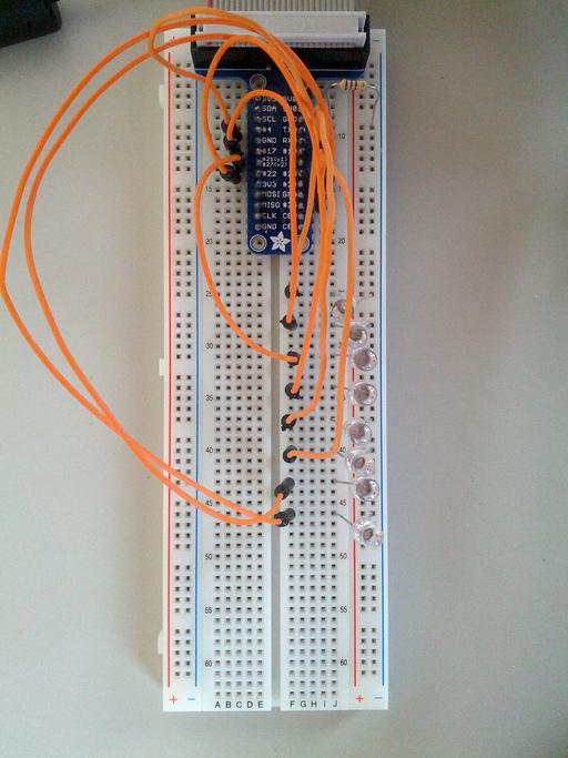
Set up the breadboard as shown: Plug the T-Cobbler into the breadboard with 13 pins in the E column and 13 pin in the G column. Use the jumper wires
to connect pins 4, 17, 27, 22, 18, 23, 24 and 25 to evenly spaced free rows lower on the breadboard. Connect 8 blue LEDs from each jumper wire row to
the blue - column, with the flattened cathode side on the blue - column. Complete the circuit by connecting the resistor from the blue - column to the GND pin.
Connect the ribbon cable to the T-Cobbler and the Raspberry Pi correctly, and turn on your Raspberry Pi.
The GPIO interface requires root privilege for access so the Wolfram Language or Mathematica needs to be started as root for this experiment.
In a terminal start the Wolfram Language using the following command (as root):
> sudo wolfram
Wolfram Language (Raspberry Pi Pilot Release)
Copyright 1988-2013 Wolfram Research
Information & help: wolfram.com/raspi
In[1]:=
First we define the pins that correspond to connected LEDs:
pins = {4,17,27,22,18,23,24,25}
Next we can turn on individual LEDs by writing the value '1' to it:
DeviceWrite[ "GPIO", First[pins] -> 1 ]
And of course turn it back off, by writing the value '0':
DeviceWrite[ "GPIO", First[pins] -> 0 ]
Or turn the LEDs on and off one at a time:
Do[
DeviceWrite[ "GPIO", pins[[i]]->1 ];
Pause[.2];
DeviceWrite[ "GPIO", pins[[i]]->0 ];
,{i,8}]


