Message Boards Message Boards

0
|
8905 Views
|
8 Replies
|
0 Total Likes
View groups...
Share
Share this post:
GROUPS:

New to SystemModeler - How do I smooth acceleration?

Posted 9 years ago

Hello. I'm new to SystemModeler. I'm attempting to learn the software with highly simplified experiments/models. At the moment, I'm trying to model a rotating a mass that is moved by a prismatic joint (representing a simplified hydraulic cylinder) as shown in Image1. Cartoon of mechanical arrangement to be modeled

With a combiTimeTable and position source, I animated the model. The smoothness of the combiTimeTable was set to ContinuousDerivative. The relative distance between the prismatic joint's frames, s, is shown below in Image2. This is a screen grab in Simulation Center. This is, indeed, the profile that I intended to input.

enter image description here

The velocity profile of the prismatic joint, v, is about what I expected it to be as displayed in Simulation Center. (Please see Image3) As you can see, the initial position profile that I built in Excel for the combiTimeTable is based upon nearly constant acceleration and deceleration. The velocity profile isn't quite as smooth as I'd like it to be at the end of the acceleration phase and at the start of the deceleration phase, but things here aren't horrible. My main concern relates to the acceleration profile.

enter image description here

And here is the meat of my question... When I plot the prismatic joint's acceleration, a, I get a very noisy plot. Considering my use of a combiTimeTable to control the length of the prismatic joint, can I control the filtering/averaging of the prismatic joint's acceleration? I'm quite sure I'm doing something foolish here. Thanks in advance for any help/advice that might be offered.

enter image description here

POSTED BY: Dave F
8 Replies
Posted 9 years ago

Hello Johan. I just finally found time to check your suggestion. It worked perfectly. You just helped me better understand where and when to use position, velocity, and accelerate to "drive" motions with combiTimeTables. Thank you.

I have a few more things that I'm trying to sort out. If I can't these things sorted through on my own today - I may post about these stumbling blocks soon.

Again, thank you for so kindly helping me get past my combiTimeTable confusion.

Dave

POSTED BY: Dave F
Posted 9 years ago

Dave, after looking at your spreadsheet I see that you start by defining the acceleration and then calculate the speed and position from that. In that case I'd use an Accelerate component, with: Modelica.Mechanics.Rotational.Sources.Accelerate accelerate(phi.start = 3.141592) and "drive" the model that way.

Attachments:
POSTED BY: Johan Rhodin
Posted 9 years ago

Hi Johan,

Thank you very much for the help. I can't believe that in all of my playing around with this, I never actually checked the documentation for the Position source. Your reply was very helpful.

So the resulting revolute acceleration in SystemModeler looks like this: enter image description here

The acceleration profile used to build my position table looked like this: enter image description here

Understanding now how the acceleration profile is developed by the Position source, it seems that I either have to live with the acceleration approximation that results from a position input table or, perhaps, use a Speed or Accelerate source with an appropriate table when I'm inclined to use a combiTimeTable input for one reason or another.

Before I close out this question in my mind, may I ask you for your advice here? Suppose that a customer or employer of mine sends me the excel sheet that I attached in my earlier post. If I need to use this tabulated motion profile with a SystemModeler model, what would be the most accurate way to drive the revolute? Should I use a combiTimeTable to input position, speed, or acceleration to the revolute and use some appropriate f_crit filter frequency? Should I fit a curve to the tabulated position, speed, or acceleration data and then use a RealExpression block with an appropriate rotational source? Or is there a better way to "instruct" the SystemModeler revolute to accurately follow the motion profile in excel that I'm not thinking of?

Thank you for all of your help!

POSTED BY: Dave F
Posted 9 years ago

Dave, I quickly looked at your model. You're using a Modelica.Mechanics.Rotational.Sources.Position to drive the revolute joint. Position has to somehow derive the angular velocity and acceleration from the numerical input. From the documentation of Position:

The reference angle is filtered and the second derivative of the filtered curve is used to compute the reference acceleration of the flange. This second derivative is not computed by numerical differentiation but by an appropriate realization of the filter. For filtering, a second order Bessel filter is used. The critical frequency (also called cut-off frequency) of the filter is defined via parameter f_crit in [Hz]. This value should be selected in such a way that it is higher as the essential low frequencies in the signal.

I changed the f_crit in a simplifed version of your system to 0.1, and that gave a nice angular velocity and acceleration.

Model with revolute and position

Attachments:
POSTED BY: Johan Rhodin
Posted 9 years ago

Hello Johan and SystemModeler Community,

This post revives an old thread. I was forced to set my System Modeler learning process aside for about a month until backlog at work eased up. I’m back at it now.

To simplify things a bit after my first post, I changed the CombiTimeTable input from the Prismatic joint length to the Bod Box’s pivot point (Revolute0). All of my previous concerns/questions still apply. In the following discussion, I am looking only at the position, velocity, and acceleration plots of the Resolute0 joint being driven by a CombiTimeTable and Rotary Position Source.

I started this project by creating a simple motion profile in excel. (File attached.) Over a 60 second total time interval, the profile assumes constant acceleration for 20 seconds, zero acceleration for twenty seconds, and constant deceleration for twenty seconds. I used the resulting radial joint position (in radians) to create the input CombiTimeTable to drive the position of Revolute0 in System Modeler.

When I run the simulation and plot the relative rotation angle of Revolute0 (phi), I get a plot that looks like the input that I built in excel. (This is hardly amazing. I’m just looking at the position input into SystemModeler.) Then, when I check the rotational velocity of Revolute0 (first derivative of phi), I get a velocity profile that matches that of my original excel spreadsheet closely, but not perfectly. Then, when I look at the angular acceleration of Revolute0, the plot gets “noisy” - especially around the acceleration step changes at 20, 40, and 60 seconds. Through the “noise”, you can see that SystemModeler is following the acceleration profile that was originally created in my excel spreadsheet, but significant inaccuracies (“noise”) are superimposed on the acceleration profile.

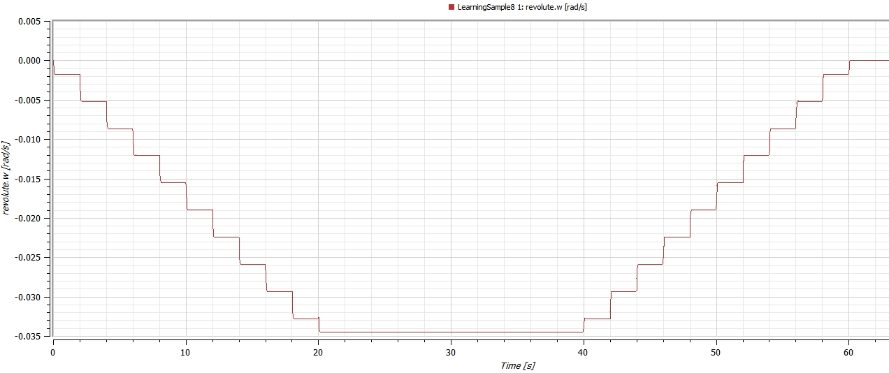
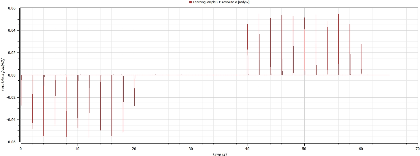
I assume that this noise/inaccuracy is a result of the position input table that I’m using. When I set the smoothness of combiTimeTable position input to “Linear Segments” I get the following stair-step angular velocity plot – as expected. When I look at the angular acceleration, I get discontinuous spikes as shown below. I appreciate why the angular acceleration plot looks the way it does (a result of the velocity discontinuities) – but I’m trying to figure out how to get it to match the actual (non spiky) acceleration profile used to create the position input table.

Velocity with Smoothness set to Linear Segments Acceleration with smoothness set to Linear Segments

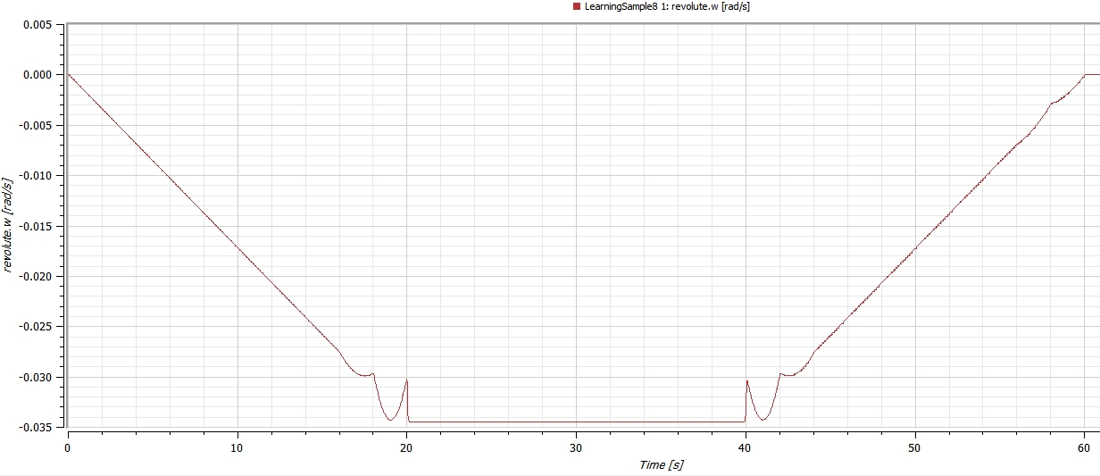
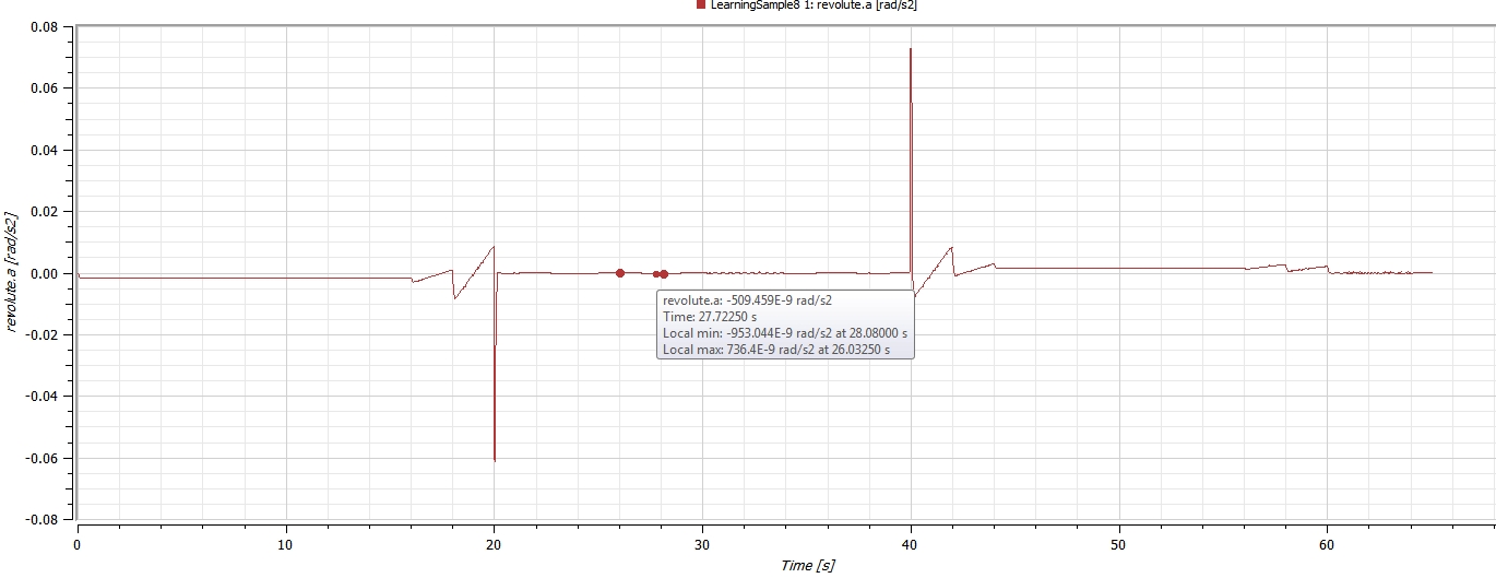
Changing the combiTimeTable Smoothness to “Continuous Derivative” improves the situation a bit. The angular velocity plot (shown below) now looks close to the one in excel. The concern here relates to the inaccurate profile that results at the acceleration step changes (at 20 seconds, 40 seconds, and 60 seconds). Not only is the angular velocity profile inaccurate, the acceleration profile is too.

Velocity with smoothness set to Continuous Derivative Acceleration with smoothness set to Continuous Derivative

I’m sure that I’m not using SystemModeler properly. I know what the acceleration and velocity profiles look like that correspond to the position profile that I fed into SystemModeler via the CombiTimeTable. Since I do not know how to get SystemModeler to output velocity and acceleration profiles that match those that I used in excel, I’m not yet comfortable using SystemModeler to analyze motions and forces of things that I’m not already familiar with or have otherwise studied.

For Example: Let’s say that I want to investigate the motion and forces at Resolute1 in the attached model. Right now, if I use the velocity, acceleration, and force data from SystemModeler as inputs to a bearing engineering/design effort, I’ll be using bogus input data. My present use of a combiTimeTable to drive the mechanism’s motion leads to inaccurate velocity and acceleration profiles at various mechanism points. Clearly this is a problem. So let’s say that I’m handed the desired motion profile of a mechanism's “part A” in an excel table by my boss or by a customer and I’m tasked with designing a bearing at the mechanism's connected “part B” – how do I use SystemModeler to get accurate data (forces, velocities, etc.) if my motion input table leads to inaccurate velocity and acceleration profiles throughout the model?

I did discover that I can reduce the noise in the System Modeler plots by reducing the critical filter frequency (“fcrit”) of the rotational position source (position1) to revolute0. When I lower the frequency enough to substantially eliminate the noise, the plots become less accurate. I fear that using fcrit for plot noise reduction is not the correct answer to my problem. It’s a band-aid solution to deal with the issue being introduced by the use of an input table (vs a continuous function.)

Johan brought up a great point. I suspect that adding some damping will, indeed, reduce the acceleration noise that I’m seeing. When I get further along in my modeling work and start building models that actually interest me – I will certainly include friction, damping, and other model components. But right now, I’m not trying to model anything for any particular purpose; this is just a learning exercise. It seems to me that if I build up a position profile in excel using a very simple acceleration profile and then send the resulting position profile into SystemModeler – I should be able to get velocity and acceleration profiles back out of SystemModeler that closely (or even perfectly) match those originally used to build the position input table. Until I better understand how to work with SystemModeler I’m loathe to move forward with more realistic models. I need to learn to walk before I run.

In addition to this question (a real show-stopper for me), I have a number of other questions about System Modeler’s use. I’ll post these after I get past this roadblock. Thank you for any and all assistance!

Attachments:
POSTED BY: Dave F
Posted 9 years ago

Hello Johan,

I am very sorry about this delayed response. I tried to reply about a week ago and after considerable work my computer crashed and everything was lost. Since then, I have been completely tied up with pressing work issues and haven't had the time to send a proper response. Things are still crazy here, but I will respond as soon as I can. Thanks.

Dave

POSTED BY: Dave F
Posted 9 years ago

The timetable is forcing the movement very hard. You can add a spring damper and some friction between it and the prismatic joint. Uploading your model would help bring in more advice.

POSTED BY: Johan Rhodin
Posted 9 years ago

Just in case I wasn't clear in my first post, I used a combiTimeTable source as a position input to the prismatic joint. The table is cut and pasted here for reference. Thanks.

0 2.591168 2 2.598947 4 2.622508 6 2.662497 8 2.719908 10 2.795967 12 2.891991 14 3.009233 16 3.14873 18 3.311175 20 3.496825 22 3.695442 24 3.895987 26 4.097293 28 4.298366 30 4.498345 32 4.696479 34 4.892109 36 5.084647 38 5.273567 40 5.458393 42 5.629791 44 5.779403 46 5.908291 48 6.017506 50 6.108045 52 6.180806 54 6.23656 56 6.275927 58 6.299362 60 6.307143

POSTED BY: Dave F
Reply to this discussion
Community posts can be styled and formatted using the Markdown syntax.
Reply Preview
Attachments
Remove
or Discard

Group Abstract Group Abstract