Introduction
I was inspired by the Wolfram blog by Mokashi showing how to use Mathematica to solve a 2D stationary Navier-Stokes flow using a finite difference scheme to write this blog. I thought it should be possible to solve the 2D cavity box flow problem using Mathematica's Finite Element capabilities. In the following I show how the problem can be discretized and solved by the Finite Element method using an iterative scheme.
Solving the 2D cavity flow using FE
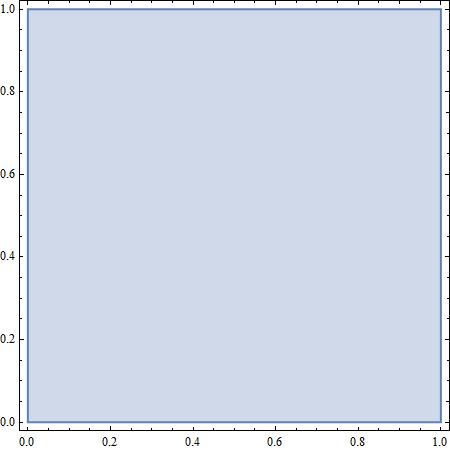
In order to solve the cavity flow problem using the finite element method, we first need to define the geometry of the box containing the fluid (the region) we want to discretize. The region is a rectangular box with width a and height b:
\[CapitalOmega] = Rectangle[{0, 0}, {a, b}] /. {a -> 1, b -> 1};
RegionPlot[\[CapitalOmega], AspectRatio -> Automatic]
In order to use the FE capabilities in Mathematica, we first have to load the FE package:
Needs["NDSolve`FEM`"]
The mesh is created using the ToElementMesh command. In our case, we only input the region to be meshed and the maximum element size. The maximum element size is specified as 1/1000 of the characteristic length. The mesh will be used to discretize the PDEs.
mesh = ToElementMesh[\[CapitalOmega], "MaxCellMeasure" -> 1/1000,
  "MeshElementType" -> QuadElement]
ToElementMesh returns a mesh object showing the bounds of the discretized region, the element type and the number of elements. The actual mesh can be displayed in wireframe using the Wireframe option:
mesh["Wireframe"]

The operator form of the 2D stationary Navier-Stokes flow
Now that we have defined the region and the mesh, we will need to input the PDEs describing our problem. Refer to the post by Mokashi to see the form of the equations. The unknowns are described by the velocity vector u and the scalar pressure field p
uv = {u[x, y], v[x, y]}; pxy = p[x, y];
The stress tensor is defined by:
\[Sigma] = -pxy IdentityMatrix[2] + 2/re Outer[ D, uv, {x, y}]*1/2
where re is the Reynolds number. The stationary N-S equations are defined by:
NS = \!\(
\*SubscriptBox[\(\[Del]\), \({x, y}\)]uv\). uv - \!\(
\*SubscriptBox[\(\[Del]\), \({x, y}\)] . \[Sigma]\);
MatrixForm[NS]
Adding the continuity condition gives the complete operator for the 2D N-S equations:
NSOperator = {NS, \!\(
\*SubscriptBox[\(\[Del]\), \({x, y}\)] . uv\)} // Flatten
It is only possible to solve a linear set of PDEs using the FE method. The operator form of the N-S equations derived above are nonlinear due to the convective terms which are products of the solution and it's derivatives. However, it is possible to linearise these terms and use an iterative scheme to calculate the nonlinear terms.Through a Newton linearization it is possible to show that:

Now, we only need to specify a reasonable starting value of u0 in order to calculate an approximation to the nonlinear term.We can now perform the next iteration by simply assigning the velocity field obtained from the last solution as an estimate to the next solution. However, we will need a criterion to terminate the iterations. A typical termination criterion would be when the flow field does not change much from one iteration to the next. This can be expressed as  where
where ![[Epsilon]](http://community.wolfram.com//c/portal/getImageAttachment?filename=eps.png&userId=382919) is a given tolerance and
is a given tolerance and  is the Norm of the velocity vector and
  is the norm of the initial velocity field from the solution of the Stokes flow.
Boundary conditions
The boundary conditions for the 2D cavity flow in a box are given by:
bcs = {
   DirichletCondition[{u[x, y] == 1, v[x, y] == 0.}, y == 1],
   DirichletCondition[{u[x, y] == 0., v[x, y] == 0.}, x == 1],
   DirichletCondition[{u[x, y] == 0., v[x, y] == 0.}, y == 0],
   DirichletCondition[{u[x, y] == 0., v[x, y] == 0.}, x == 0],
   DirichletCondition[p[x, y] == 0., y == 1 && x == 1]};
We have prescribed no-slip conditions (u=0, v=0) at the left, right and lower side of the box. At the lid the u velocity is given by a characteristic velocity U = 1 while the v velocity is set to zero at this boundary. Since we now have specified the velocity on the complete boundary (all sides), the velocities are unique while the pressure is fixed up to one additive constant. Hence, we only need to define one additional boundary condition for the pressure. In our case we have set the pressure p=0 at the upper left corner of the box.
Solving the cavity flow problem for Re=100
Wrapping everything together, we will solve the 2D cavity flow for Reynold's number 100 in an iterative scheme. We will use the solution of the Stoke's flow as our initial velocity field. The Stokes flow is simply derived from the N-S operator neglecting the convective terms:
StokesOperator = NSOperator /. {u[x, y] -> 0, v[x, y] -> 0};
The PDEs for a Stokes flow with Reynolds number of 100:
pde = StokesOperator == {0, 0, 0} /. re -> 100;
A stable solution can be found if the velocities are interpolated with a higher order than the pressure. NDSolve allows an interpolation order for each dependent variable to be specified.
{u0, v0, p0} =
  NDSolveValue[{pde, bcs}, {u, v, p}, {x, y} \[Element] mesh,
   Method -> {"FiniteElement",
     "InterpolationOrder" -> {u -> 2, v -> 2, p -> 1},
     "IntegrationOrder" -> 5}];
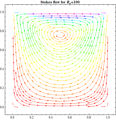
The velocity field is easily visualized using the StreamPlot function:
stokes = StreamPlot[{u0[x, y], v0[x, y]}, {x, 0, 1}, {y, 0, 1},
  StreamPoints -> Fine, StreamColorFunction -> Hue,
  StreamColorFunctionScaling -> False,
  PlotLabel ->
   Style["Stokes flow for \!\(\*SubscriptBox[\(R\), \(e\)]\)=100",
    Black, FontFamily -> "Times", Bold]]
Preparing for the iterations
To calculate the norm of the solution, wee need to access the raw solution vectors directly instead of the InterPolatingFunction returned by NDSolveValue above. We can access the raw solution vectors through the NDSolve'ProcessEquations. This will lead to a slightly more complicated work flow, but gives us access to the StateData object and it's data structure:
pde = StokesOperator == {0, 0, 0} /. re -> 100;
{state} =
 NDSolve`ProcessEquations[{pde, bcs}, {u, v, p}, {x, y} \[Element]
   mesh, Method -> {"FiniteElement",
    "InterpolationOrder" -> {u -> 2, v -> 2, p -> 1},
    "IntegrationOrder" -> 5}]
{NDSolve`StateData["<" "SteadyState" ">"]}
From the StateData object we get access to the FiniteElementData
state["FiniteElementData"]["FEMMethodData"]["Properties"]

{"DegreesOfFreedom", "ElementMesh", "IncidentOffsets", "Incidents", \
"IntegrationOrder", "InterpolationOrder", "Precision", "Properties", \
"SolutionData", "TotalDegreesOfFreedom", "VariableData"}
The IncidentOffset dataset gives us the offsets of the dependent variables in the set of the discretised PDEs:
offset = state["FiniteElementData"]["FEMMethodData"]["IncidentOffsets"]

{0, 1089, 4290, 7491}
The VariableData gives us the sequence of the dependent variables: The incidents of the first dependent variable which is the pressure p range from the first offset plus one to the second offset:
split = MapThread[#1 -> {#2} &, {vd[[3]],
   Span @@@ Transpose[{Most[# + 1], Rest[#]} &[offset]]}]

{p -> {1 ;; 1089}, u -> {1090 ;; 4290}, v -> {4291 ;; 7491}}
Now we have the necessary information to extract the raw solution for the velocity field and compute our norm for each iteration. For a steady state problem, invoking NDSolve'Iterate finds the solution of a system of equations with LinearSolve:
NDSolve`Iterate[state];
The raw solution vector is now available from the StateData object:
sol = state["FiniteElementData"]["Solution"];
The raw velocity vector can be extracted dropping the pressure terms from the solution vector:
uv0 = Drop[sol, First[p /. split]];
We store the vector for using it to compute the norm in the next iteration.
{u0, v0, p0} = {u, v, p} /. NDSolve`ProcessSolutions[state]
This returns three interpolating functions which are assigned to u0, v0 and p0. The velocity field can be visualized using the StreamPlot function as showed previously.
We will now use the velocity field from the Stokes flow solution as a first guess to solve the N-S equations. We use u0 v0 from the solution of the Stokes flow as an approximation to the solution of the N-S equations:
pde = NSOperator == {0, 0, 0} /. {u[x, y] -> u0[x, y],
    v[x, y] -> v0[x, y], re -> 100};
Solving the discretized PDEs:
{un, vn, pn} =
  NDSolveValue[{pde, bcs}, {u, v, p}, {x, y} \[Element] mesh,
   Method -> {"FiniteElement",
     "InterpolationOrder" -> {u -> 2, v -> 2, p -> 1},
     "IntegrationOrder" -> 5}];
We can now display the solution of the N-S equations and compare with the Stokes solution:
GraphicsRow[{stokes,
  StreamPlot[{un[x, y], vn[x, y]}, {x, 0, 1}, {y, 0, 1},
   StreamPoints -> Fine, StreamColorFunction -> Hue,
   StreamColorFunctionScaling -> False,
   PlotLabel ->
    "Navier-Stokes flow for \!\(\*SubscriptBox[\(R\), \(e\)]\)=100"]},
  ImageSize -> Large]
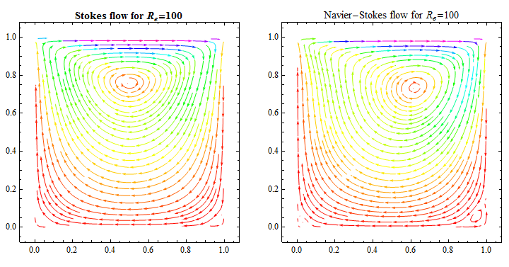
This is the first iteration, and we see that the Navier-Stokes flow field is slightly changed compared to the Stokes flow. The flow is not symmetric any more and we can see a new vortex appearing at the lower right corner.
Iterating to a converged solution
Let's progress the iteration one more step by assigning the velocity field from the last iteration as an estimate to the solution of the next iteration:
pde = NSOperator == {0, 0, 0} /. {u[x, y] -> un[x, y],
    v[x, y] -> vn[x, y], re -> 100};
{state} =
  NDSolve`ProcessEquations[{pde, bcs}, {u, v, p}, {x, y} \[Element]
    mesh, Method -> {"FiniteElement",
     "InterpolationOrder" -> {u -> 2, v -> 2, p -> 1},
     "IntegrationOrder" -> 5}];
NDSolve`Iterate[state]
Extract the velocity field from the last solution and compute the norm:
sol = state["FiniteElementData"]["Solution"];
uvn = Drop[sol, First[p /. split]];
norm = Norm[uvn - uv0]/Norm[uv0]

0.0257194
In order to visualize the solution of this iteration, we have to process the solution:
{un, vn, pn} = {u, v, p} /. NDSolve`ProcessSolutions[state];

StreamPlot[{un[x, y], vn[x, y]}, {x, 0, 1}, {y, 0, 1},
 StreamPoints -> Fine, StreamColorFunction -> Hue,
 StreamColorFunctionScaling -> False,
 PlotLabel ->
  "Navier-Stokes flow for \!\(\*SubscriptBox[\(R\), \(e\)]\)=100, \
Iteration 2. Norm = " <> ToString[norm]]
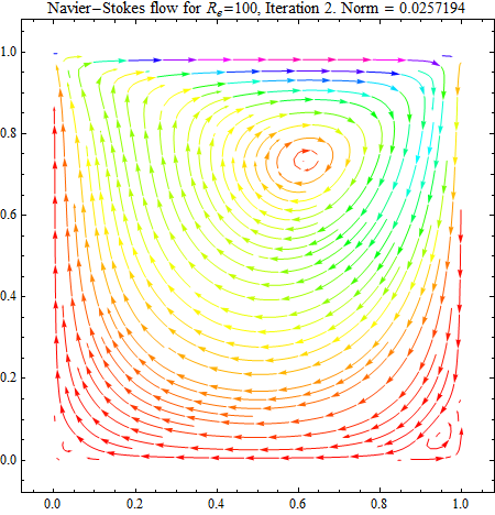
A norm of more than 2% is not small enough to accept the solution as converged, so we have to proceed with the next iteration:
uvnMinusOne = uvn;
pde = NSOperator == {0, 0, 0} /. {u[x, y] -> un[x, y],
    v[x, y] -> vn[x, y], re -> 100};
{state} =
  NDSolve`ProcessEquations[{pde, bcs}, {u, v, p}, {x, y} \[Element]
    mesh, Method -> {"FiniteElement",
     "InterpolationOrder" -> {u -> 2, v -> 2, p -> 1},
     "IntegrationOrder" -> 5}];
NDSolve`Iterate[state];
sol = state["FiniteElementData"]["Solution"];
uvn = Drop[sol, First[p /. split]];
norm = Norm[uvn - uvnMinusOne]/Norm[uv0]

{un, vn, pn} = {u, v, p} /. NDSolve`ProcessSolutions[state];

StreamPlot[{un[x, y], vn[x, y]}, {x, 0, 1}, {y, 0, 1},
 StreamPoints -> Fine, StreamColorFunction -> Hue,
 StreamColorFunctionScaling -> False,
 PlotLabel ->
  "\!\(\*SubscriptBox[\(R\), \(e\)]\)=100, Iteration 3. Norm = " <>
   ToString[norm]]
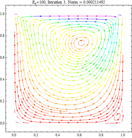
We see that the norm is less than 10^-3, and we may accept the last iteration as a converged solution. We have now solved the fully non-linear Navier-Stokes equations for a 2D cavity flow.
I hope this small demonstration can be of inspiration to others. The big advantage of using the FE method is the flexibility of the method to discretize non-regular region geometries. This will allow us to solve 2D Navier-Stokes flows for much more complex geometries. I might return with some examples in a future post.
Ole Christian