The following text summarizes the process of development of a truss diagram visual analyser
Abstract
The problem behind the developing a visual analyser is to improve the first stages of development of structures for buildings, sculptures, airplanes, etc. The first step is to translate the diagram image file to a data structure that is easily computed. Afterwards, the data structure information will fill some slots in an array and some computation can be done to come up with functions and vectors for all the forces of the structure. Finally, the information is displayed in a nice interface.
Introduction
The following text describes the development of truss diagram analyser. The text goes through the different stages of the development giving multiple examples and the rasons for the codes design solutions. The motivation behine the development of such project is to aid and facilitate the process of building design for architecs and civil engineers. However, this does not mean that this tool replaces more specialized and sophisticated software and models. For this same reason the scope of this project is to aid the first stages of the development of buildings and structures that required trusses. The long term goal for this project is to be able to take a picture of a sketch of a truss diagram a use this tool to go through all the physical analysis
The final design for this project is to create a program capable to input a image file ( could be a picture on the long run) and output the dynamics (forces) analysis based on the geometric characteristics of the structure inside the picture. The choossen strategy to tackle this project was to devide the problem into two: visual processing and dynamics analysis.
Steps
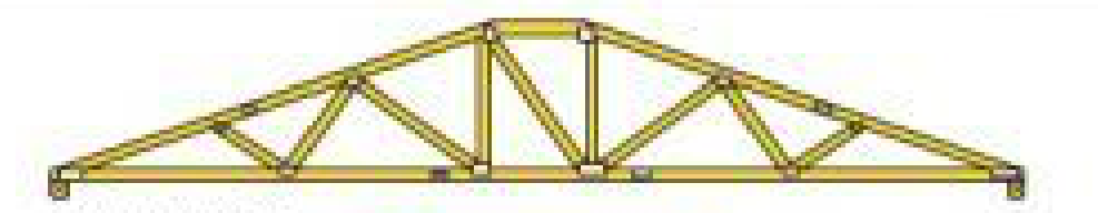
- Step 1 The first part of the development of the visual analyser is to translate an image file to a computable structure. This process can be either archived by a machine learning approach or a built-in function, such as morphology. In other words, the program inputs an image file and the output is a computable structure. The approach used for the first version of this program is the use a series of filters in order to get the best input from for the MorphologicalGraph function. This functions takes an image and outputs a graph that is useful for computations.
The first part of this process the diagram is imported.
    diagram =
     ImageCrop[ImageCrop[trusses, {500, 130}, {Right, Top}], {500, 115},
      Bottom]
After the image is imported to Mathematica the image is transformed using multiple filters.
    binaryDiagram =
     Dilation[ColorNegate[
       Binarize[ImageEffect[diagram, {"Posterization", 2}]]], 1]

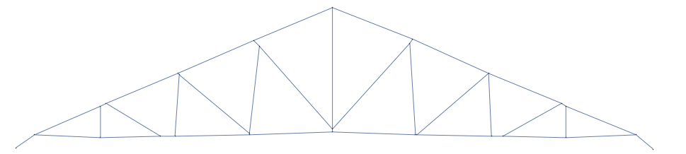
After finding the proper filter, this filtered image is transformed to a not-perfect graph.
originalGraph = MorphologicalGraph[binaryDiagram]
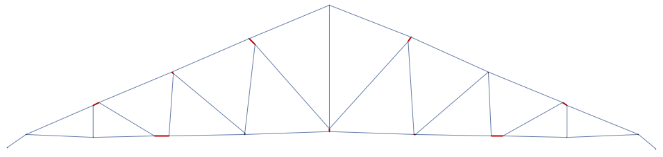
In order to correct the small mistakes made by the MorphologicalGraph function an algorithm that uses machine leaning (more precisely Cluster function) and underling assumptions in order to delete these small defects in the graph. In the following image the red nods are the sections that the algorithm correctly found that had to be deleted.
- Step 2 Once the image is normalized, the graph has embedded useful information necessary to model the whole structure. The first part of this process is to create the necessary list in order to compute and solve for all the forces. This list have a combination of parameters inputted by the user and some derived from the graph.
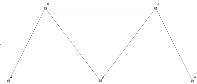
Here we have the structure of the main forces list.The atomic structure of this list is composed by a list of a magnitude force and the angle (vector force list) relative to the positive x axis . The next layer of this list is composed by clusters of the vector force list acting on particular vertex. Finally, the composition of the next layer represents the forces acting in the whole structure.
    {{{F[a b], 1.10715}, {F[a c], 0.}, {S1, \[Pi]/2}, {Sp, 0}}, {{F[a b],
       4.24874}, {F[b d], 0.}, {F[b c], 5.35589}, {FS1, (3 \[Pi])/
       2}}, {{F[b d], 3.14159}, {F[d e], 5.17604}, {F[c d],
       4.06889}, {FS3, (3 \[Pi])/2}}, {{F[d e], 2.03444}, {F[c e],
       3.14159}, {S2, \[Pi]/2}}, {{F[a c], 3.14159}, {F[b c],
       2.2143}, {F[c d], 0.927295}, {F[c e], 0.}, {FS2, (3 \[Pi])/2}}}
Through different transformation of this list, the information encoded in here and using the method of joints from classical mechanics [Note:1] a new list of equations can be created to input into the function of Solve.
{Sp + 0.447214 F[a b] + 1. F[a c] == 0,
 0. + S1 + 0.894427 F[a b] ==
  0, -0.447214 F[a b] + 0.6 F[b c] + 1. F[b d] == 0,
 0. - FS1 - 0.894427 F[a b] - 0.8 F[b c] ==
  0, -1. F[b d] - 0.6 F[c d] + 0.447214 F[d e] ==
  0, -FS3 + 1.22465*10^-16 F[b d] - 0.8 F[c d] - 0.894427 F[d e] ==
  0, -1. F[c e] - 0.447214 F[d e] == 0,
 S2 + 1.22465*10^-16 F[c e] + 0.894427 F[d e] ==
  0, -1. F[a c] - 0.6 F[b c] + 0.6 F[c d] + 1. F[c e] == 0,
 0. - FS2 + 1.22465*10^-16 F[a c] + 0.8 F[b c] + 0.8 F[c d] == 0}
Once all all the known and unknown variables are set up in a equation list, the function Solve is used to solve for all the missing variables.
Solve[equations,forces]
{{F[a b] -> 0. - 0.894427 FS1 - 0.559017 FS2 - 0.223607 FS3,
  F[a c] -> 0.4 FS1 + 0.25 FS2 + 0.1 FS3,
  F[b d] -> -0.25 FS1 - 0.625 FS2 - 0.25 FS3,
  F[b c] -> -0.25 FS1 + 0.625 FS2 + 0.25 FS3,
  F[d e] -> -0.223607 FS1 - 0.559017 FS2 - 0.894427 FS3,
  F[c d] -> 0.25 FS1 + 0.625 FS2 - 0.25 FS3,
  F[c e] -> 0.1 FS1 + 0.25 FS2 + 0.4 FS3,
  S1 -> 0.8 FS1 + 0.5 FS2 + 0.2 FS3,
  S2 -> 0.2 FS1 + 0.5 FS2 + 0.8 FS3,
  Sp -> -2.19291*10^-16 FS1 + 1.8619*10^-16 FS2 + 1.24127*10^-17 FS3}}
The solutions are dependent on the input forces.
- Step 4 Once the all the forces are properly solved, an interfaced is implemented.
Requirements A data base of at least 80 truss diagrams is going to be required to complete the first part of the projects. For the second and third part a knowledge of analysis of truss is required.
[1:Note] For more information about the joint method check the following link.


