Introduction
When an origami design is unfolded, the resulting lines left on the paper are called crease patterns. Single vertex crease patterns (patterns where all the folds emanate from a single point), are governed by Kawasaki's Theorem which states that the sum of all odd angles and even angles are both 180 degrees. This demonstration allows the user to explore the various possible folding patterns that are generated from a class of very simple single vertex crease pattern. It is a Mathematica implementation of the cover demonstration from the RabbitEar Origami Coding Design Library: https://rabbitear.org/ All code is original and was written without referencing the code for the original demonstration.
Creating the Square Diagram
The demonstration works by taking a user input for the center point via a locator and generating a flat folding diagram based off that point. The first 3 lines are automatically defined to come from 3 of the vertices of the square. The last line is dynamically calculated with the use of various functions:
First the Law of Cosines is used to calculate the center angles.
LOC[x_, y_, z_] := N[ArcCos[(x^2 + y^2 - z^2)/(2 x y)]];
To calculate the distances for the law of cosines, a simple function that calculates euclidean distance was created
TwoDDistance[{ax_, ay_}, {bx_, by_}] :=
  N[Sqrt[Abs[ax - bx]^2 + Abs[ay - by]^2]];
Based on the constraints of Kawasaki's theorem and the calculated angle, the direction angle for the line form the center point can be calculated with some simple geometry:
findDirectionAngle[{ax_, ay_}] := (Pi - LOC[TwoDDistance[{ax, ay}, {-1, 1}], TwoDDistance[{ax, ay}, {1, 1}], 2] - N[ArcTan[{ax + 1}/{ay + 1}] ]) - Pi/2
With the direction angle and some algebra, we can generate expressions to determine where the fourth line intersects the edge of the square. This requires an if statement to account for the fact that the intersection point can be either on the bottom or right edge of the square.
findSquareEdgeIntersect[a_, {px_, py_}] :=
 Module[{bx, by},

  bx = ((-1 - py)/Tan[a]) + px;
   by = -1;
  If[bx <= -1,
   by = N[(Tan[a] (1 - px)) + py];
   bx = 1;
   Return[{bx, by}],

   If[bx >= 1,
    by = N[(Tan[a] (1 - px)) + py];
    bx = 1;
     Return[{bx, by}],

     Return[{bx, by}]
    ]
   ]
  ]
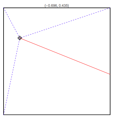
The resulting intersection point can be added to a simple locator based manipulate to generate an interesting visual of the valid crease pattern for any user selected center point.
Manipulate[

 Graphics[{
   Style[RegularPolygon[Sqrt[2], 4], EdgeForm[Thick], White],
   Blue, Dashed, Line[{{-1, -1}, p}],
   Line[{{-1, 1}, p}],
   Line[{{1, 1}, p}],
   Red, Dashing[None],
   Line[{p, findSquareEdgeIntersect[findDirectionAngle[p][[1]], p]}]

   },

  PlotRange -> 1,
  PlotLabel -> p,

  PlotRangePadding -> None

  ],

 {{p, {0, 0}}, Locator}


 ]
Here is a sample output:
Basic Folding Tools
In order to emulate the folded shape of a paper, we can split the square into polygons along all edges and fold lines, and then reflect these polygons over their respective fold lines. Reflection of polygons in Mathematica can be done with the creation of a reflection matrix. Very handily, Mathematica can calculate the relevant reflection matrix, but to correctly employ this, we must also translate each polygon so that the line going through a folded edge goes through the origin because reflection matrices reflect across mirrors going through the origin. For this purpose we must calculate the y intercept of each of the important folded lines.
findYintercept[a_, {px_, py_}] := (-px)*Tan[a] + py]

bottomLeftYint [{px_, py_}] := py - ( (py + 1)*px/(px + 1));
(*finds the y intercept of the line from (-1,-1) to p *)

topLeftYint[{px_, py_}] := py + px (1 - py)/(1 + px);
(*finds the y intercept of the line from (-1,1) to p *)
The above function takes in a direction angle a (generated by an earlier function) and the coordinates of the center point and calculates the y intercept of the fourth fold line.
I also created functions to return the correct right and bottom polygons (because of the two cases)
Rightplygnchecker[p_] :=(*p_ represents the locator point*)

 Block[{bx, by},
  {bx, by} = findSquareEdgeIntersect[findDirectionAngle[p][[1]], p];
  If[bx == 1,
   Return[{Polygon[{p, {1, 1}, {bx, by}}]}],
   Return[{Polygon[{p, {1, 1}, {1, -1}, {bx, by}}]}]
   ]
  ]

Bottomplygnchecker[p_] := (*p_ represents the locator point*)

 Block[{bx, by},
  {bx, by} = findSquareEdgeIntersect[findDirectionAngle[p][[1]], p];
  If[bx == 1,
   Return[{Polygon[{p, {-1, -1}, {1, -1}, {bx, by}}]}],
   Return[{Polygon[{p, {-1, -1}, {bx, by}}]}]
   ]
  ]
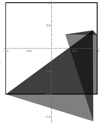
We can put these parts together to create a static folded image given coordinates for center point (which was arbitrarily named r)
Graphics[
 {
  Style[Rectangle[{-1, -1}, {1, 1}], White, EdgeForm[Thick]],

  Style[Bottomplygnchecker[r], Opacity[0.5]],

  GeometricTransformation[

   GeometricTransformation[

    GeometricTransformation[
     Style[Rightplygnchecker[r], Opacity[0.5]],


     TranslationTransform[{0, -findYintercept[findDirectionAngle[r],
          r][[1]]}]],

    ReflectionMatrix[{
      Tan[findDirectionAngle[r]][[1]]
      , -1}]],

   TranslationTransform[{0,
     findYintercept[findDirectionAngle[r], r][[1]]}]],


  GeometricTransformation[

   GeometricTransformation[

    GeometricTransformation[
     {Style[Polygon[{{-1, -1}, {-1, 1}, r}], Opacity[0.5]],
      GeometricTransformation[
       GeometricTransformation[
        GeometricTransformation[
         Style[Polygon[{{-1, 1}, r, {1, 1}}], Opacity[0.5]],
         TranslationTransform[{0, -topLeftYint[r]}]],

        ReflectionMatrix[{  (r[[2]] - 1)/(1 + r[[1]]), -1}]
        ], TranslationTransform[{0, topLeftYint[r]}]]

      },
     TranslationTransform[{0, -bottomLeftYint[r]}]],


    ReflectionMatrix[{
      (r[[2]] + 1)/(r[[1]] + 1)
      , -1}]],

   TranslationTransform[{0, bottomLeftYint[r]}]]


  },
 Axes -> True
 ]
When r= {0.4,0.2}, the above code produces:
Putting Everything in a Manipulate
For the purpose of shorthand, a generalized function FoldedShape that could accept arguments for color and opacity for pairs of polygon, as well as image size, was created.
FoldedShape[r_, C1_, C2_, O1_, O2_, opts_] := Graphics[
  {
   (*Style[Rectangle[{-1,-1},{1,1}],White,EdgeForm[Thick]], *)

   Style[Bottomplygnchecker[r], Opacity[O1], C1],
   (* COLOR 1 *)
   GeometricTransformation[

    GeometricTransformation[

     GeometricTransformation[
      Style[Rightplygnchecker[r], Opacity[O2], C2],
      (*Color 2*)

      TranslationTransform[{0, -findYintercept[findDirectionAngle[r],
           r][[1]]}]],

     ReflectionMatrix[{
       Tan[findDirectionAngle[r]][[1]]
       , -1}]],

    TranslationTransform[{0,
      findYintercept[findDirectionAngle[r], r][[1]]}]],


   GeometricTransformation[

    GeometricTransformation[

     GeometricTransformation[
      {Style[Polygon[{{-1, -1}, {-1, 1}, r}], Opacity[O2], C2],
       (*Color 2*)

       GeometricTransformation[
        GeometricTransformation[
         GeometricTransformation[
          Style[Polygon[{{-1, 1}, r, {1, 1}}], C1, Opacity[O1]],
          (*COLOR 1*)

          TranslationTransform[{0, -topLeftYint[r]}]],

         ReflectionMatrix[{  (r[[2]] - 1)/(1 + r[[1]]), -1}]
         ], TranslationTransform[{0, topLeftYint[r]}]]

       },
      TranslationTransform[{0, -bottomLeftYint[r]}]],


     ReflectionMatrix[{
       (r[[2]] + 1)/(r[[1]] + 1)
       , -1}]],

    TranslationTransform[{0, bottomLeftYint[r]}]]


   },
  (*Axes\[Rule]True,*)
  opts
  ]
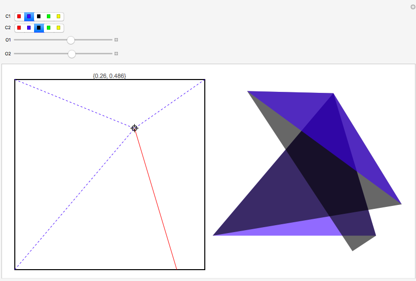
Then, this function was added to the original flat folding crease pattern manipulate.
Manipulate[
 Row[{
   Graphics[{
     Style[RegularPolygon[Sqrt[2], 4], EdgeForm[Thick], White],
     Blue, Dashed, Line[{{-1, -1}, p}],
     Line[{{-1, 1}, p}],
     Line[{{1, 1}, p}],
     Red, Dashing[None],
     Line[{p,
       findSquareEdgeIntersect[findDirectionAngle[p][[1]], p]}]
     },
    (*   z=findSquareEdgeIntersect[findDirectionAngle[p][[1]],p]; *)

       PlotRange -> 1,
    PlotLabel -> p,
    (*   PlotLabel\[Rule]z, *)
    (*If you are interested in \
confirming the location of the intersection of the intersection of \
the fourth line with the square you can un comment the z definition,
    and replace the PlotLabel\[Rule]p with PlotLabel\[Rule]z   *)
    \

    (*Axes\[Rule]True, *)
    PlotRangePadding -> None,
    ImageSize -> {400, 400}
    ],
   FoldedShape[p, C1, C2, O1, O2, ImageSize -> {400, 400}]
   }
  ],

 {{p, {0, 0}}, {-.99, -.99}, {.99, .99},
  Locator}, {C1, {Red, Blue, Black, Green, Yellow}}, {C2, {Red, Blue,
   Black, Green, Yellow}}, {{O1, 0.3}, 0, 1}, {{O2, 0.3}, 0, 1}

 ]
Future Work
There are some interesting possibilities for future extensions. At the current moment, the only movable object in the base simulation is the central locator point. By allowing the user to change some of the more fundamental angles and lines, the program could become even more engaging and interesting. Along this vein, a whole host of other similar single vertex folding demonstrations could also be created.
Perhaps more in the future, the mechanisms implemented in this project for "polygon folding" via Mathematica could be extended to fully emulate other origami folding programs, and would ideally be capable of drawing a 2d shape for any foldable pattern.
Closing
Special thanks to my mentor Michael Kaminsky, and Rob Morris for helping me create this. I have also attached two notebooks. First, "Everything to run" which contains only the code necessary if you would like to run the manipulate yourself, and "Origami Demonstrations Documentation" which has full documentation and explanation for each step of my project.
 Attachments:


