I draw a lot of system architecture diagrams showing how different blocks of software interact, sometimes with physical components, sensors, etc.
Normally I draw these diagrams using PowerPoint, although sometimes I will use Adobe Illustrator. Sometimes I combine the two by pasting pieces from one or the other into the other. Every once in a while I use Adobe Photoshop if images are involved and Illustrator doesn't cut it.
In reviewing changes in Mathematica 8 I notice that they added align and distribute functions to the drawing tools, which would seem to move Mathematica more towards a professional drawing capability. My question is: to what extent could I replace Illustrator/PowerPoint and do software architecture diagrams in Mathematica? Would Mathematica have specific abilities for creating such diagrams not present in the standard tools?
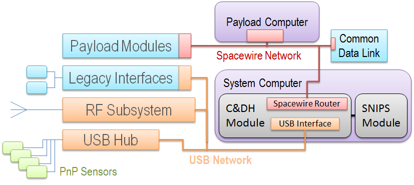
Here is an example of a typical architectural diagram:

Some of the areas/questions that are relevant:
* ability to create rounded, 3D looking boxes and buttons
* ability to create and copy styles of various types
* ability to create freeform connectors and arrows
One thing that really drives me nuts in PowerPoint is that their right angle connectors only have a limited set of configurability. You can't make arbitrary right-angle connections. For example you can create Z-like shape but you cannot create a U-like shape. You can actually see this in the diagram above. I have to jimmy together a bunch of different connectors to get the paths as shown. In some cases you can see the seams where the different connectors touch. How would Mathematica do drawing such connectors for example?
I understand that Mathematica is not supposed to be a drawing tool, but nevertheless am interested in the extent to which it can act as one.