Authors : @Frederick Wu @Shenghui Yang
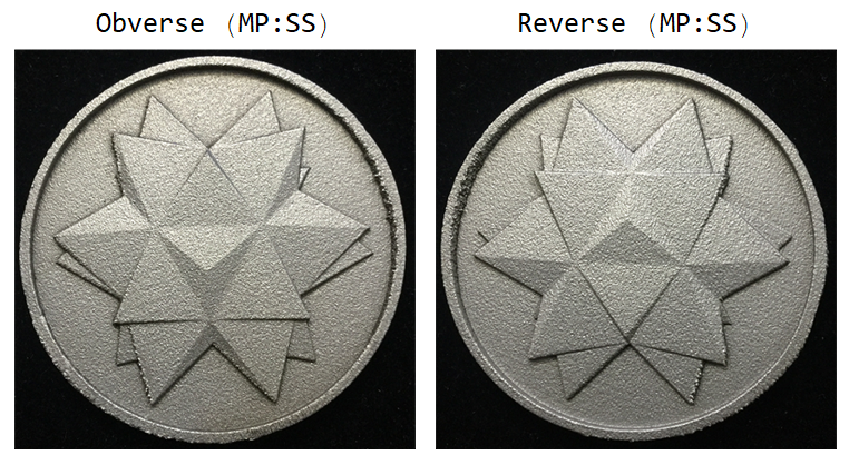

One day my friend ShengHui Yang from Wolfram Alpha approached me and suggested that I could make a physical Wolfram Spikey Coin (not to confuse with Wolfram Blockchain Token ;-) ), as for the celebration for the 30th anniversary of Mathematica. As a long-term Mathematica user and coin collector, I challenged myself to design my own commemorative coin for such a special event.

The iconic Spikey is a life-long companion of Mathematica since Version 1, coined (no pun intended) in 1988. We come to a time that Wolfram technologies and different 3D Printing processes happily marry together in 2018.
1. Introduction
Traditional coin casting is low-relief design. It is the optical orthogonal projection that makes viewers feel the sculpture raised from the background plane and creates a vivid 3D optical illusion with minimum model depth. Usually, the relief depth plane can be set between front plane of the object and the vanishing plane. A low-relief compresses the model in axial direction (perpendicular to the background plane) in the scale ratio ranging from 0.02 to 0.1, a high relief from 0.1 to 0.2, and a super-high-relief greater than 0.3.
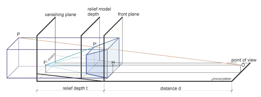
I crafted a Demonstration Projects Applet (Design Your Own Commemorative Coin) to illustrate some cool coin designs using aforementioned orthogonal projection and 3D geometric scaling method. The user can freely set the view point, the level of relief plane and the scaling ratio. Here there is a list of geometric objects available in the applet:
subjectList = {"Spikey", "BassGuitar", "Beethoven", "CastleWall",
   "Cone", "Cow", "Deimos", "Galleon", "HammerheadShark", "Horse",
   "KleinBottle", "MoebiusStrip", "Phobos", "PottedPlant", "Seashell",
    "SedanCar", "SpaceShuttle", "StanfordBunny", "Torus", "Tree",
   "Triceratops", "Tugboat", "UtahTeapot", "UtahVWBug", "Vase",
   "VikingLander", "Wrench", "Zeppelin"};
Here there is a list of materials and colors available. The texture of the metal affects the reflection and color of the coin:
material = {"Pt", "Au", "Ag", "Cu", "Ni", "Ti", "Al", "Zn"};
color = ColorData["Atoms"][#] & /@ material;
materialColor =
  Thread[Rule[color,
    Row[{#[[1]], " ", #[[2]]}] & /@ Transpose[{material, color}]]];
Extract the 3D body configuration of the Spikey through ExampleData.
modelFun[object_] :=
  If[object == "Spikey", PolyhedronData["Spikey", "GraphicsComplex"],
   ExampleData[{"Geometry3D", object}, "GraphicsComplex"]];
Create 3D models of coins and add controls to the applet: 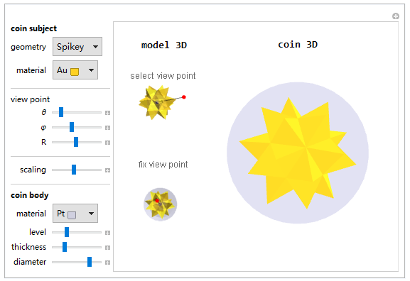
Programming in Wolfram Language provides a simple way to evaluate the accuracy of a relief model against a real 3D model. Think about the test as if you handhold a solid 3D spikey and rotate it so the spikey can coincide with the configuration in the relief above. Meanwhile the scaling effect is how close you hold the spikey to your eye. What we mean about same configuration is that the grey impression on the left was as if made by the right object punching through the round piece. Like aligning a palm with the impression after a face slap.

To quantify the scaling effect, run the following code to generate three pieces of graphical information:
region3DRaw = PolyhedronData["Spikey", "Region"];
region3D =
  TransformedRegion[region3DRaw, RotationTransform[3, {1, 1, 1}]];
region3DTr =
  TransformedRegion[region3D,
   ScalingTransform[.2, {0, 0, 1}, {0, 0, 0}]];
- The left graphics is a view of a real 3D spikey object (2D projection onto our retina).
- The middle one is a relief model from same view point but the model is "squeezed" (moved back and forth) with a certain scaling ratio along a certain vector. The vector is in the direction of a given view point and center of the object.
- The right image is the image difference between the 3D object and the relief object. It counts difference pixels in image range.
    SetOptions[{Region}, Boxed -> False, ViewPoint -> {0, 2, 10},
      BaseStyle -> {Gray, EdgeForm[Thick]},
      PlotRange -> {{-2, 2}, {-2, 2}, {-2, 2}}, AspectRatio -> 1,
      Lighting -> {"Directional", White}, ImageSize -> 400 {1, 1}];

    threeDim = Region[region3D];
    reliefDim = Region[region3DTr];
    Export["threeDim.png", threeDim];
    Export["reliefDim.png", reliefDim];
    imageThreeDim = Import["threeDim.png"];
    imageRelief = Import["reliefDim.png"];
    diff = Binarize@ImageDifference[imageThreeDim, imageRelief];

    Grid[{Style[#, 14] & /@ {"real 3D object", "relief model",
        "image pixel difference"},
      Framed /@ {imageThreeDim, imageRelief, ColorNegate@diff}}]
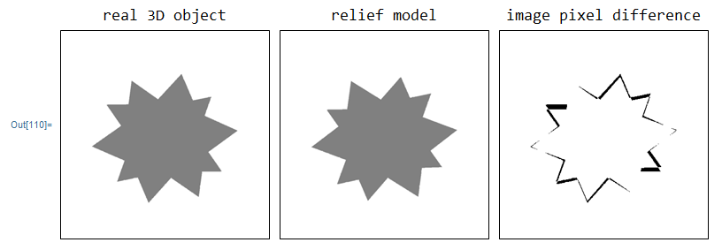
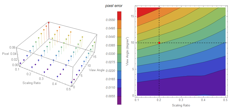
Further numerical analysis can be carried out with the code below, shown in the list plot on the left and right contour shown numerically. On the right graph, for example, we choose a red point on the cross:
- A 3D model compressed at scaling ratio 0.2 and becoming a relief model.
- An observer views the relief model within a view angle range, deviated from the center vector less than 10 degrees.
It generates only 3.3% pixel error in boundary. In other words, the relief model used 20% depth of the 3D object to create 96.7% 3D effect.
2. Design
We have come a long way, but the job is not finished yet. There is small clearance between the spikey and coin body. So I need to fill the gap in geometry. First, I get the spikey region model, I also rotate the Spikey a little bit to create a non-symmetric pattern for artistic reasons.
SetOptions[{Region}, Boxed -> False, ViewPoint -> Automatic,
  BaseStyle -> {Pink, EdgeForm[Thick]},
  PlotRange -> All, AspectRatio -> 1, Lighting -> "Neutral",
  ImageSize -> 400 {1, 1}];
SpikeyRegion = PolyhedronData["Spikey", "Region"];
SpikeyRegion3D =
  TransformedRegion[
   TransformedRegion[SpikeyRegion, RotationTransform[E, {E, Pi, E}]],
   ScalingTransform[12 {1, 1, 1}, {0, 0, 0}]];
Row[{Column[{"Spikey Top View",
    Region[SpikeyRegion3D, ImageSize -> 250 {1, 1},
     ViewPoint -> {0, 0, 100}]}, Alignment -> Center],
  Column[{"Spikey Bottom View",
    Region[SpikeyRegion3D, ImageSize -> 250 {1, 1},
     ViewPoint -> {0, 0, -100}]}, Alignment -> Center]}]
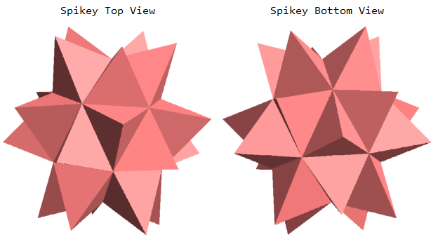
Here I pull each face of the triangle or polygon along the Z direction.
regionData = Table[MeshPrimitives[SpikeyRegion3D, i], {i, 0, 2}];
transGroup =
  Table[Table[
    Map[(# + {0, 0, i}) &, regionData[[3]][[j]][[1]]], {i, 0, 50,
     50}], {j, Length@regionData[[3]]}];
I use ConvexHull to generate prism-like polyhedrons from each triangle.
Grid@Partition[
  Take[convexhullMesh = ConvexHullMesh[Flatten[#, 1]] & /@ transGroup,
    16], 8]
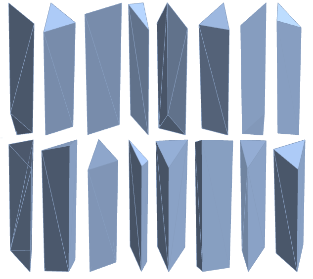
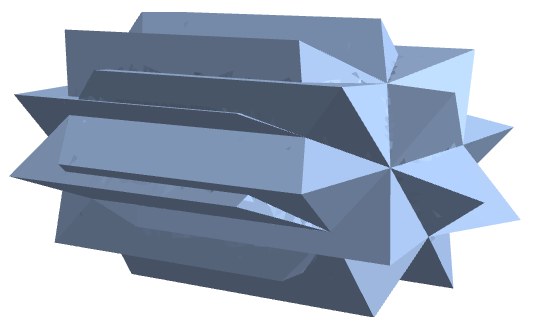
Now, I use RegionUnion to join all generated prism-like polyhedrons together, It becomes a pulled long Spikey, but without changing the front and back side geometry.
regionUnion1 =
  Table[BoundaryDiscretizeRegion[
    RegionUnion @@ Take[convexhullMesh, {3 (i - 1) + 1, 3 (i)}]], {i,
    1, 20}];
regionUnion2 =
  Table[RegionUnion @@ Take[regionUnion1, {5 (i - 1) + 1, 5 i}], {i,
    4}];
convexhullUnion =
 RegionUnion[RegionUnion[regionUnion2[[1]], regionUnion2[[4]]],
  RegionUnion[regionUnion2[[2]], regionUnion2[[3]]]]
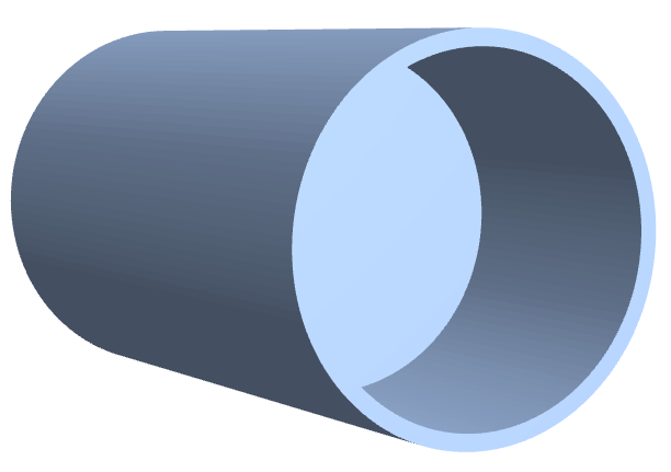
Below I use RegionProduct to prepare a coin body with an outside protective ring.
regularPolygonMesh[r_Integer, n_Integer] :=
  BoundaryMeshRegion[
   Table[r {Cos[k 2 \[Pi]/n], Sin[k 2 \[Pi]/n]}, {k, n}],
   Line[Append[Range[n], 1]]];

r1 = 21;
r2 = 23;
h1 = 25 + 41.5;
h2 = 25 - 41.5;

annulus =
  RegionDifference[regularPolygonMesh[r2, 2*64],
   regularPolygonMesh[r1, 2*64]];
line = Line[{{h2}, {h1}}];
tube = BoundaryDiscretizeRegion[RegionProduct[annulus, line]];

d1 = 25 - 7.5;
d2 = 25 + 7.5;
bottomPlate =
  BoundaryDiscretizeRegion[
   RegionProduct[regularPolygonMesh[r2, 2*64], Line[{{d1}, {d2}}]]];

assembly = RegionUnion[bottomPlate, tube]
Then I compress the 3D pulled Spikey into a relief model and export STL file for 3D printing. This transformation process takes about 10 seconds to complete.
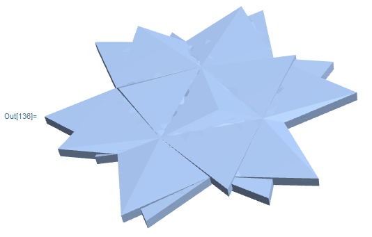
Printout3D[SpikeyRelief, "SpikeyRelief" <> ".stl",
 RegionSize -> Quantity[40, "Millimeters"]]
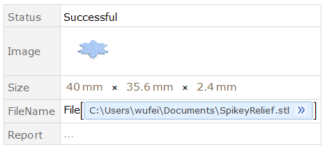
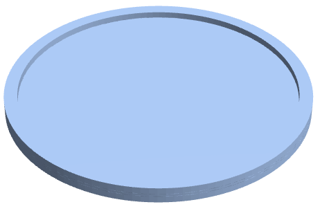
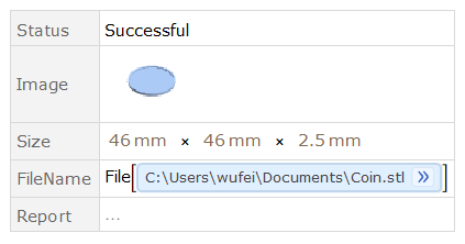
Similarly, we compress the 3D pulled coin into a coin model and export STL file for 3D printing. Later I will join the relief model and the coin model together. Usually, the coin ring is a little bit thicker than the relief height, so that the outside ring can protect the relief patterns and resist abrasion.
Coin = TransformedRegion[assembly,
  ScalingTransform[0.03, {0, 0, 1}, {0, 0, 0}]]
Printout3D[Coin, "Coin" <> ".stl",
 RegionSize -> Quantity[46, "Millimeters"]]
3. Visualizing
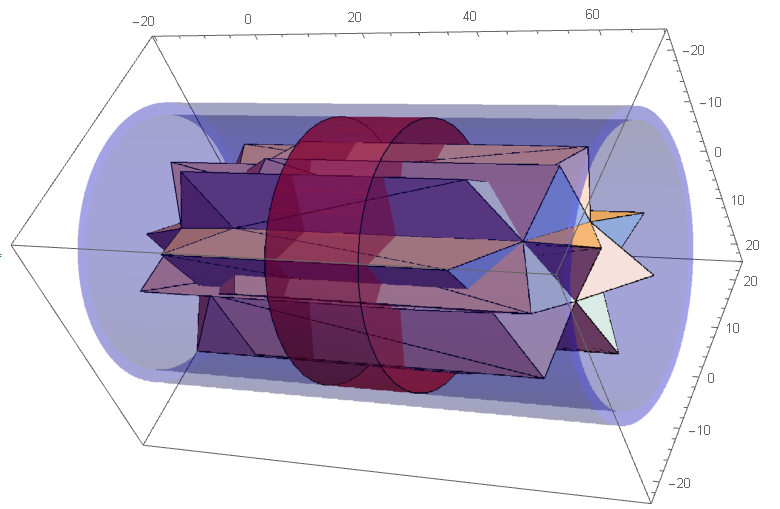
Let's take a glance at the whole model. The concept of coin design is "Breakthrough" or "Penetration". It looks like, the spikey breaks or travels through a coin plate in space and time.
convexhullData =
  MeshPrimitives[ConvexHullMesh[Flatten[#, 1]], 2] & /@ transGroup;

Graphics3D[{convexhullData, Opacity[.5], Red,
  Cylinder[{{0, 0, 25 - 8}, {0, 0, 25 + 8}}, r1],
  Blue, Opacity[.2], EdgeForm[None], MeshPrimitives[tube, 2]},
 Axes -> True, ImageSize -> {600, 400}]
Set scale ratio is 0.025, and compress the 3D model into the relief model.
scale = 0.025;
subject =
  GeometricTransformation[{convexhullData},
   ScalingTransform[scale, {0, 0, 1}, {0, 0, 0}]];
body = GeometricTransformation[{Cylinder[{{0, 0, 25 - 7.5}, {0, 0,
       25 + 7.5}}, r1]},
   ScalingTransform[scale, {0, 0, 1}, {0, 0, 0}]];
ring = GeometricTransformation[{MeshPrimitives[tube, 2]},
   ScalingTransform[scale, {0, 0, 1}, {0, 0, 0}]];
coin3D = Graphics3D[{ EdgeForm[None], ColorData["Atoms"]["Au"],
   subject, White, body, ring }, Lighting -> Red, Boxed -> False,
  ImageSize -> 400 {1, 1}]

vp = {{0, -Infinity, 0}, {-Infinity, 0, 0}, {0, 0, Infinity}, {0,
    0, -Infinity}, {-1, -.1, 2}, {-1, -.1, -2}};
Grid[Partition[Table[
   Graphics3D[{EdgeForm[None], Specularity[Brown, 100],
     ColorData["Atoms"]["Cu"], subject,
     LightBlue, Specularity[Red, 100], body,
     Opacity[If[i == 1 || i == 2, .01, 0.9]], ring},
    Axes -> If[i <= 4, True, False], Boxed -> If[i <= 4, True, False],
     PlotRange -> Automatic,
    AxesLabel -> (Style[#, 12, Bold] & /@ {"x", "y", "z"}),
    ImageSize ->
     Which[i == 1, {300, 100}, i == 2, {300, 100},
      i == 3, {300, Automatic}, i == 4, {300, Automatic},
      i == 5, {300, Automatic}, i == 6, {300, Automatic}],
    ViewPoint -> vp[[i]]], {i, 1, Length@vp}], 2], Spacings -> 5]
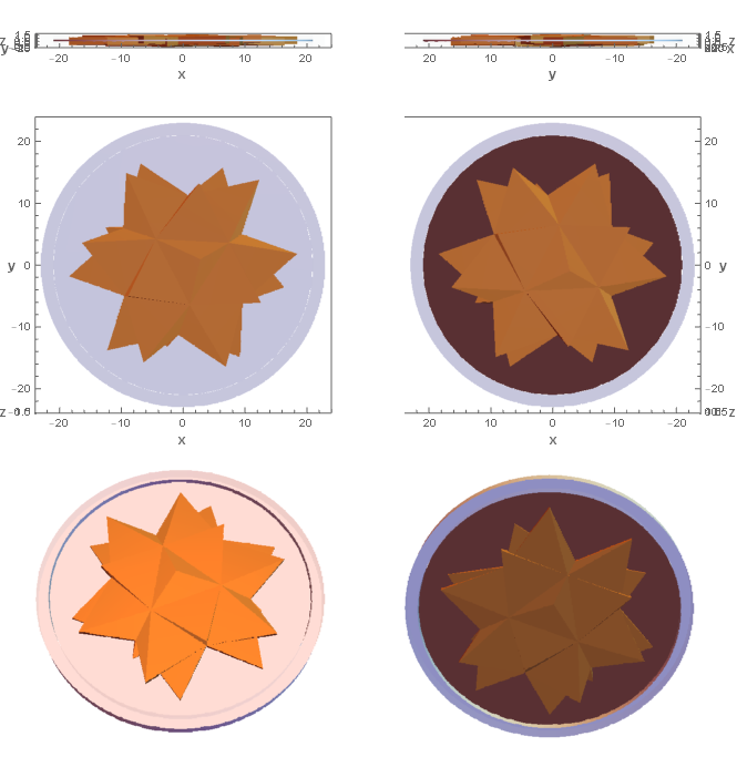
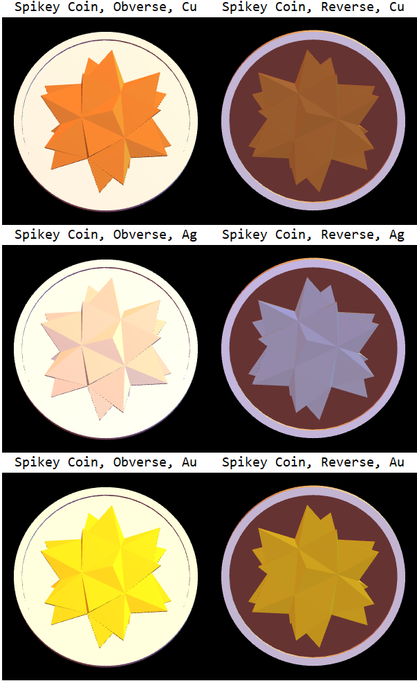
As the concept of "Breakthrough" or "Penetration", the spikey should go through a coin plate. The two sides of the coin pattern (obverse and reverse) look similar, but they are not exactly the same. They are the front view {0, 0, Infinite} and the back view {0, 0, -Infinite} of the same Spikey.
Column[Row[{Column[{Style["Spikey Coin, Obverse, " <> #[[2]], 20],
       Graphics3D[{EdgeForm[None], Specularity[#[[1]], 50],
         ColorData["Atoms"][#[[2]]], subject, White, body, ring},
        Boxed -> False, ViewPoint -> {-1.5, -2, 10},
        ViewAngle -> Pi/30, Background -> Black,
        ImageSize -> 300 {1, 1}]}, Alignment -> Center],
     Column[{Style["Spikey Coin, Reverse, " <> #[[2]], 20],
       Graphics3D[{EdgeForm[None], Specularity[#[[1]], 50],
         ColorData["Atoms"][#[[2]]], subject, White, body, ring},
        Boxed -> False, ViewPoint -> {-1.5, -2, -10},
        ViewAngle -> Pi/30, Background -> Black,
        ImageSize -> 300 {1, 1}]}, Alignment -> Center]
     }] & /@ {{Brown, "Cu"}, {White, "Ag"}, {Yellow, "Au"}}]
4. 3D Printing and Prototypes
4.0 3D Model Quality
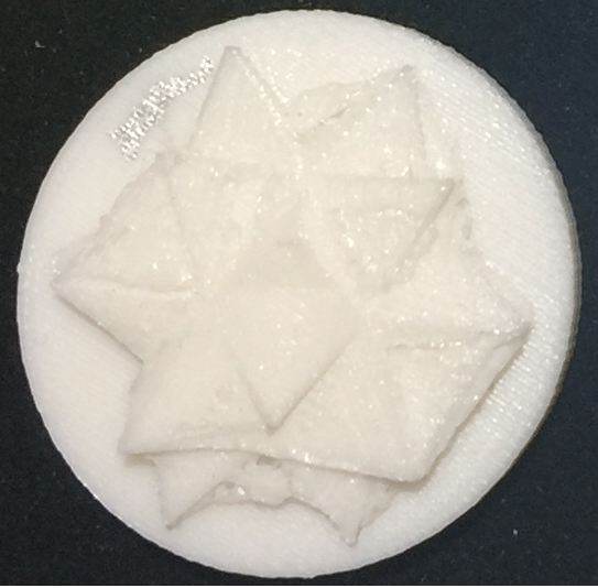
My very first printed sample was bad. It was a Graphics3D-based model, so it has all faces glued together.
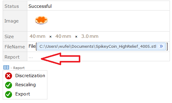
Then, I struggled to improve the model quality, move them into region-generated, discretization and defects should be checked and passed.
4.1 FDM (Fused Deposition Modeling)
FDM (Fused Deposition Modeling) is most widely used 3D printing technology works with thermoplastics at low cost, but it also has a relatively low accuracy.
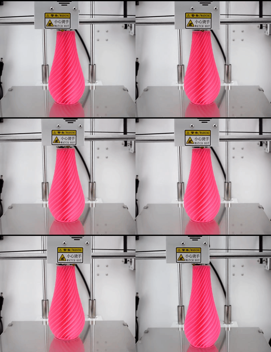
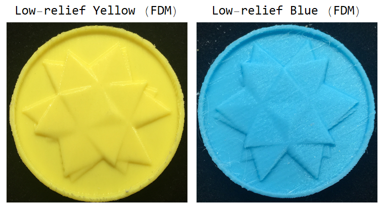
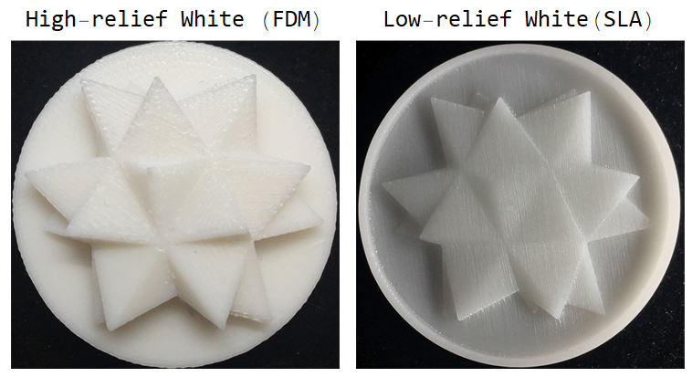
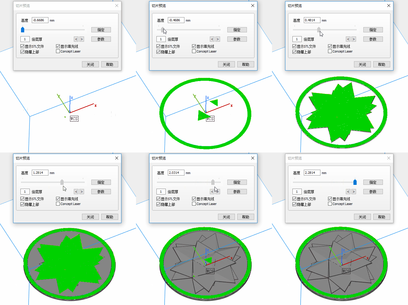
I set the model in horizontal placement for high relief coin. It looks OK. But for low relief and thin parts, I later changed the placement to vertical or tilted attitude.
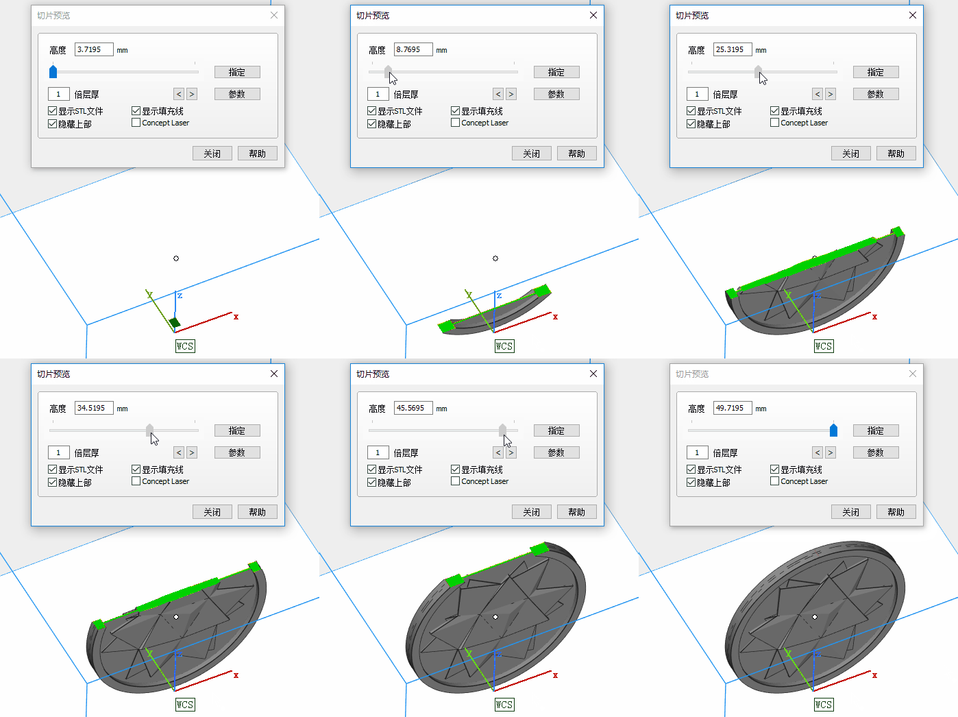
4.2 SLA (Stereo-lithography)
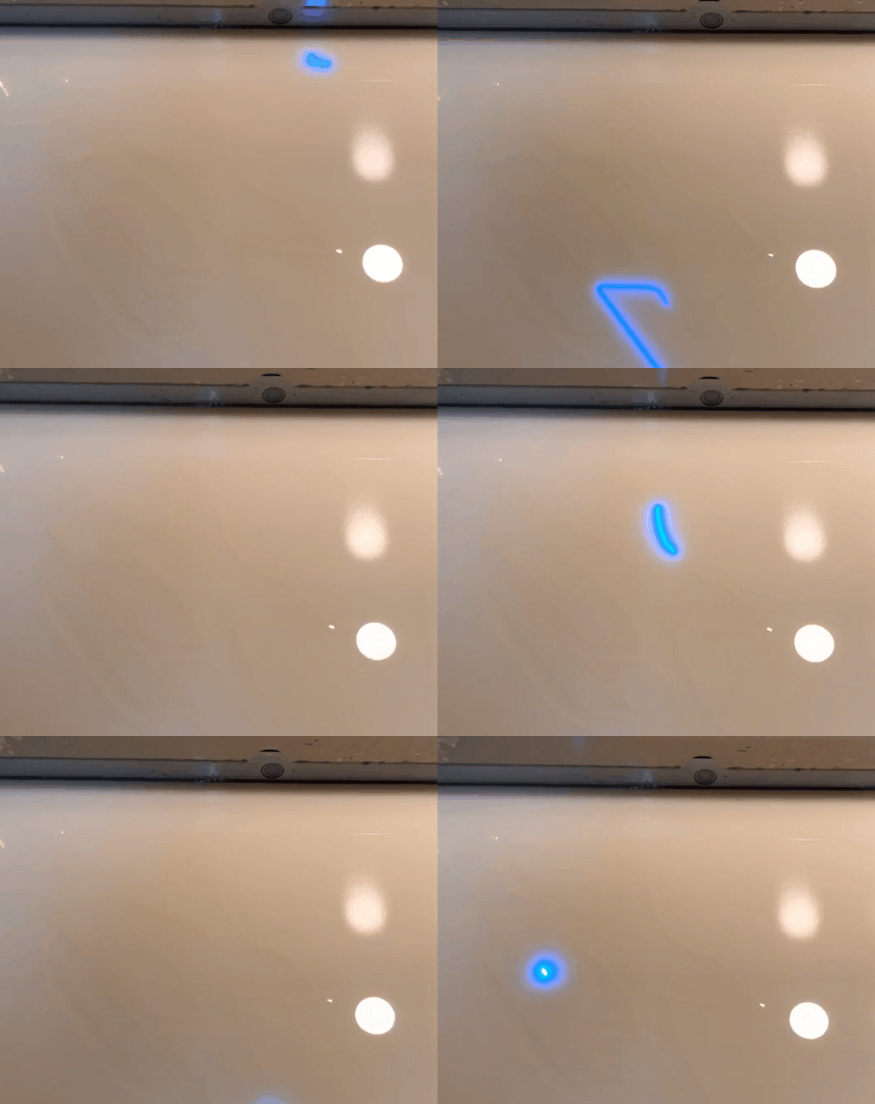
SLA (Stereo-lithography) is also 3D printing technology by using ultraviolet light to cure photosensitive polymers. Its advantage is that it has a higher accuracy in comparison to FDM.
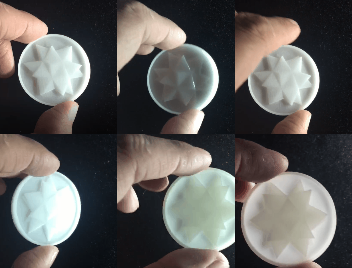
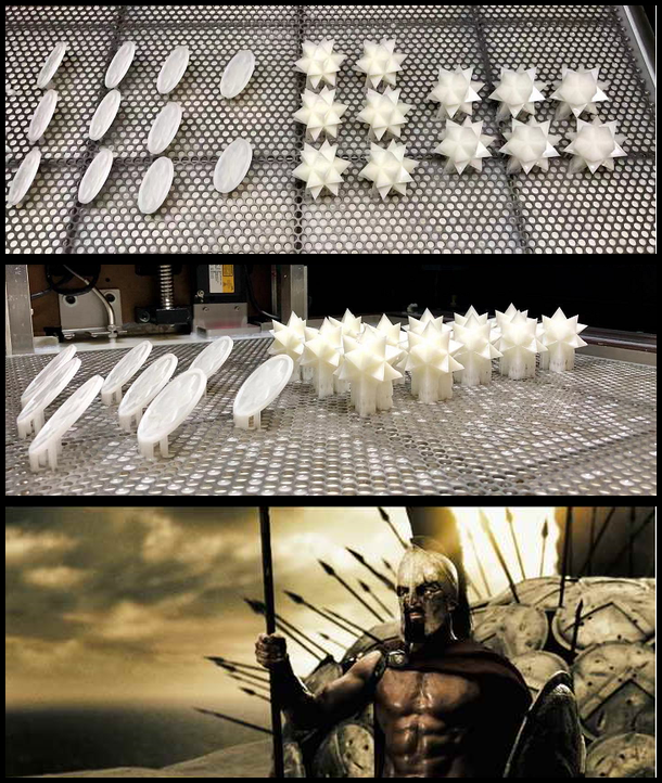
If many Spikey 3D models and Spikey coins are printed together, they look like a square of Spartan warriors holding sharp spears and shields.
4.3 MP (Metal Powder)
Metal powder is a 3D printing process with a high accuracy and high cost, it is like a powder bed fusion and directed energy deposition grew at an explosive pace.
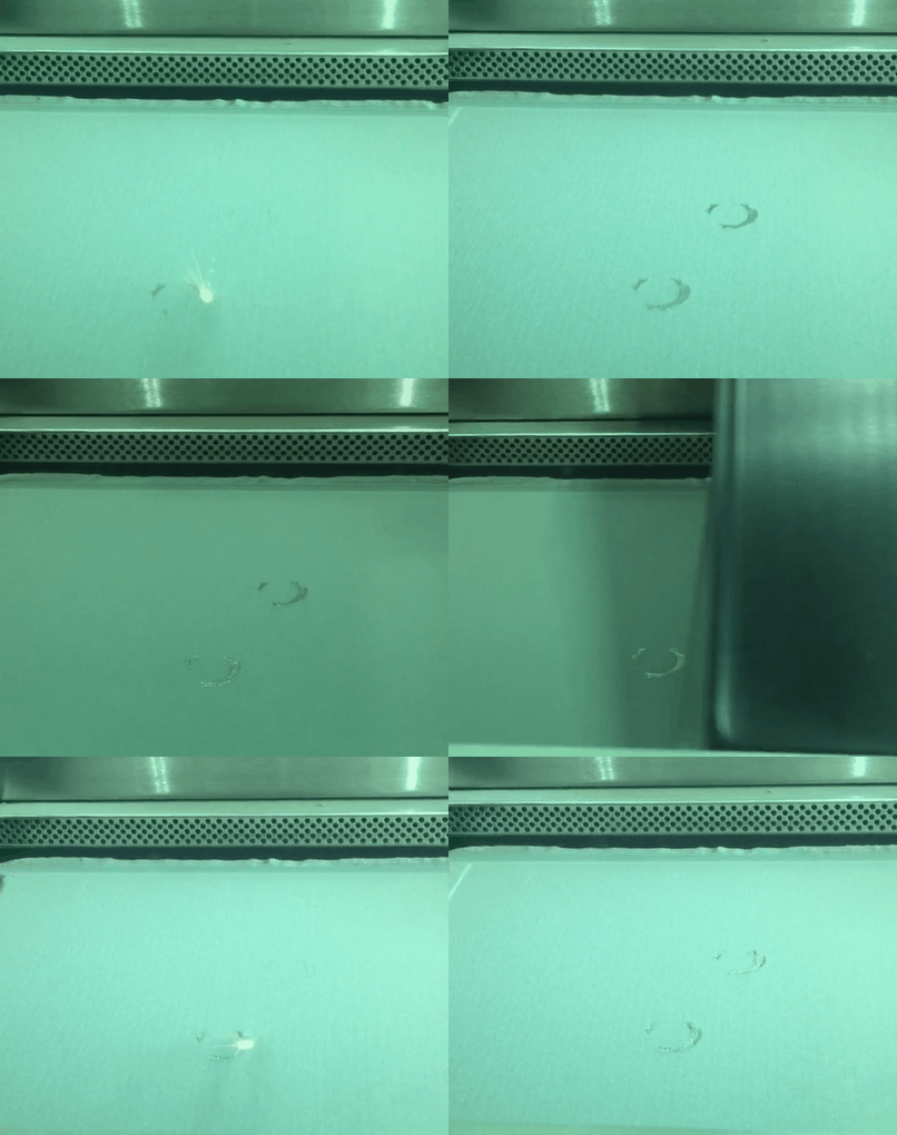
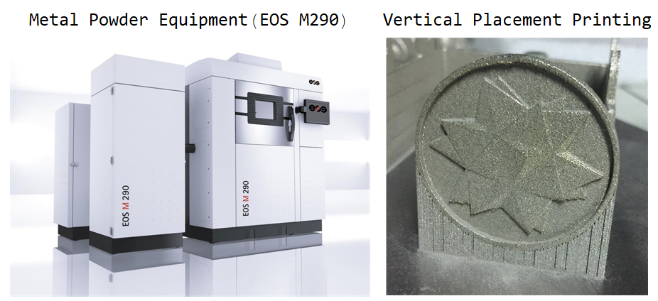
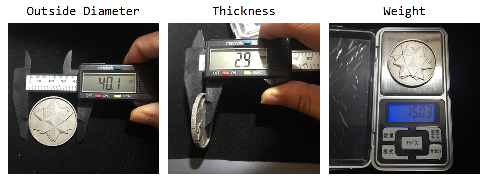
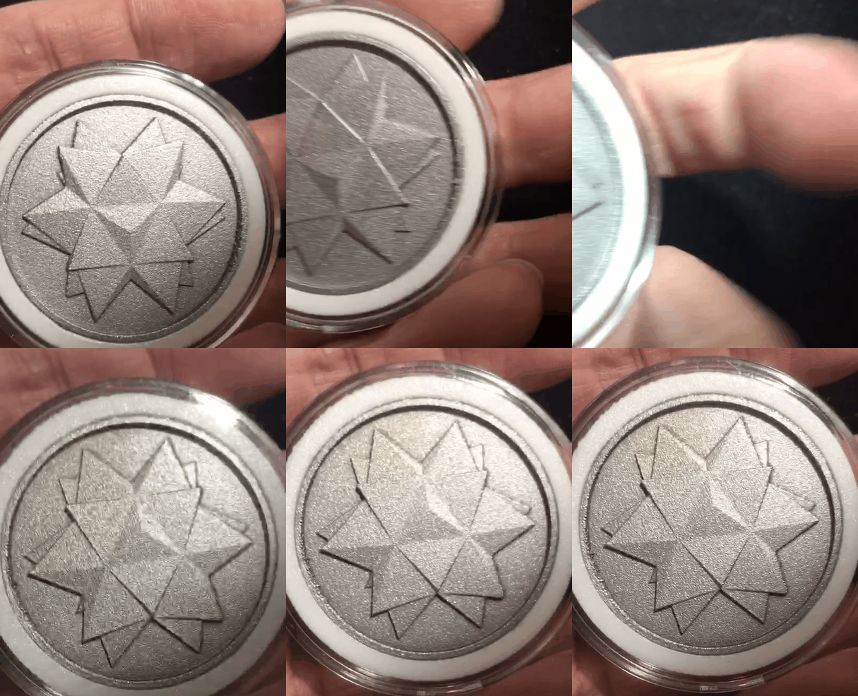
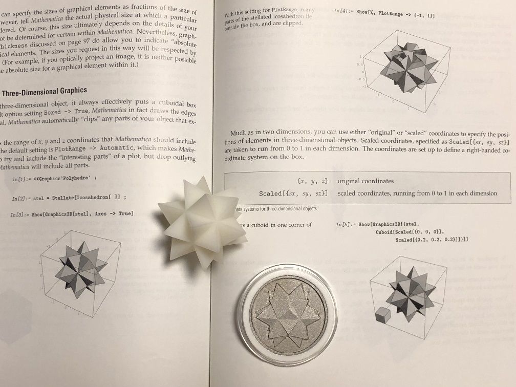
I also printed in metal powder processing with German equipment of EOS M 290. It's a 1 million dollars equipment with advanced additive manufacturing technology. The printed coins are made in material of stainless steel power. It has 40 mm outside diameter and 3 mm thickness, with thinnest region at coin plate only 0.5mm. It weights 15 grams. As you can see from the metal spikey coin, the relief pattern is clearly distinguishable. All faces of triangle form an optical diffuse reflection.


4.4 Tips for 3D Printing
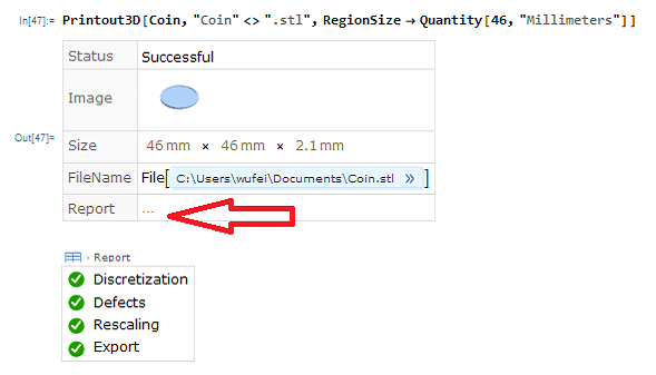
- 3D printing model should be in good quality. Export STL from Graphics3D is not good enough for 3D printing. Region is much better and restrict define. You can kick Printing3D report and check your model quality. Discretization and defects should all be checked and passed.
- For a thin model, horizontal placement (background plane is put flat on the printing table) results a poor resolution in sculpture. Vertical or tilted placement wold helps to increase printable layers and improve detail resolution in the relief.
5. Greetings
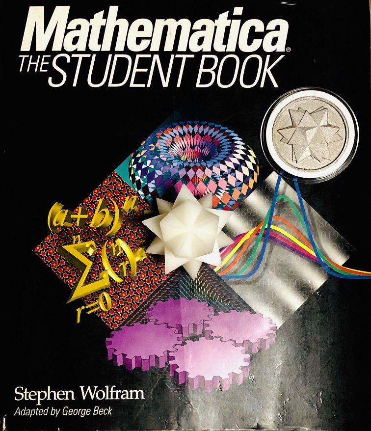
This project was supported a lot friends. Thank you to all my friends in Wolfram China Community. Finally, Yang and my family would like to share some images below for this moment as holiday greetings to all world-wide friends in Wolfram Community.



 Attachments: