Perhaps this:
(* transfer function *)
tf = (1/2 s + 1/10)/s // Simplify;

(* the input *)
in = LaplaceTransform[Sin[w t], t, s];

(* output in t domain *)
outt = InverseLaplaceTransform[tf in, s, t];

(* the integral of the output in the t domain *)
(* note division by s to get integral *)
outtIntegral = InverseLaplaceTransform[tf in/s, s, t];

(* the mean value over the first n periods of the input *)
Simplify[outtIntegral/n /. t -> n 2 Pi/w, n \[Element] Integers]

(* \[Pi]/(5 w^2) *)
Edit: Sorry, the integral was over t = 0 to n 2 Pi/w, so that is the normalization period.
(the mean value over the first n periods of the input)
Simplify[outtIntegral/(n 2 Pi/w) /. t -> n 2 Pi/w,
 n \[Element] Integers]

 (* 1/(10 w) *)
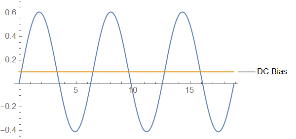
Edit: A numerical example with w = 1
dcBias = NIntegrate[outt /. w -> 1, {t, 0, 6 Pi}]/6/Pi

(* 0.100 *)

Plot[{outt /. w -> 1, Callout[dcBias, "DC Bias"]}, {t, 0, 6 Pi}]