Message Boards Message Boards

0
|
2833 Views
|
5 Replies
|
4 Total Likes
View groups...
Share
Share this post:

Using input and output connectors from a sub-model as connectors of a larger model

Posted 1 year ago

I have a model with input and output connectors, and I'd like to know if there's a way to use the same connectors as inputs and outputs of another model that contains it.

For example, consider this model:

model InputOutputInterior
  Modelica.Blocks.Math.Power power1 ;
  outer Modelica.Blocks.Interfaces.RealInput u ;
  outer Modelica.Blocks.Interfaces.RealOutput y ;
equation
  connect(power1.y, y) ;
  connect(u, power1.u) ;
end InputOutputInterior;

and the model that contains it:

model InputOutputExterior
  inner Modelica.Blocks.Interfaces.RealInput u ;
  inner Modelica.Blocks.Interfaces.RealOutput y ;
  InputOutputInterior inputOutputInterior1 ;
end InputOutputExterior;

In the second model, with the declaration of the connectors as inner, I was aiming to indicate that the connectors InputOutputInterior.u and InputOutputInterior.y are also connectors for the model InputOutputExterior.

The compiler gives the following error:

Error: InputOutputInterior [7:3-7:3] Invalid connect-equation. inputOutputInterior1.u is an outer connector, it cannot be used in a connect-equation.
Error: InputOutputInterior [6:3-6:3] Invalid connect-equation. inputOutputInterior1.y is an outer connector, it cannot be used in a connect-equation.

The reason for asking this question is that the model I'm working with, will have many sub-models, each one with input and output connectors that don't need to be connected to other sub-models, and could be considered as inputs and outputs for the larger model. Adding additional connectors for each one in the larger model seems unnecessarily cumbersome, and I'd like to avoid it.

Any suggestions on how to use inner and outer properly in this case, or an alternative solution (e.g. expendable connectors), would be appreciated.

Cheers,

Fabián

POSTED BY: Fabián Peña
5 Replies
Posted 1 year ago

Dear Ankit,

Thank you very much for the new reply. Your suggestions have been very useful.

Based and inspired by both of your suggestions, I came up with a solution that seems to be a good compromise given the restrictions I have.

An important restriction is that the connectors in the exterior model must not be connected, both visually and logically. Not connecting them avoids visual cluttering due to the potentially large number of connections, and logically, it's necessary for them to be recognized as input and output ports of the overall system.

Using inner and outer declarations, as in one of the examples, indeed avoids the visual cluttering, but the input and output connectors are still connected logically via the inner and outer variables.

What I did was to define a new connector, containing all the signals each interior model (i.e. IOInterior class in the example below) requires, and used it as interface between the each IOInterior instance and the exterior model IOExterior.

Inside the class IOInterior, I used an additional class, called CableTie, to route the signals into the new connector. Formally, this class is not necessary, but having them allows visual representation of the connections rather than just equations written in text. The equations are written instead within in the CableTie class.

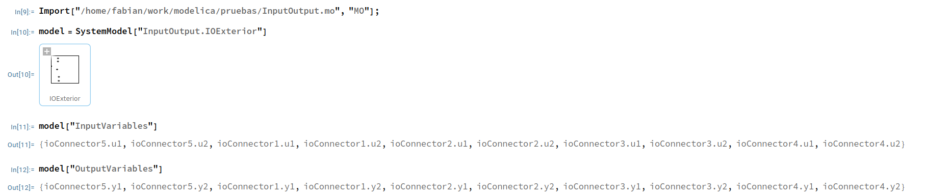
As shown in the following screenshot, Mathematica recognizes the input and output variables defined in the new connector and, therefore, they can be used to calculate transfer functions:

enter image description here

Thank you very much again.

Cheers,

Fabián

The model is this:

package InputOutput
  model IOExterior
    IOInterior ioInterior1 annotation(Placement(visible = true, transformation(origin = {0, 0}, extent = {{-10, -10}, {10, 10}}, rotation = 0)));
    IOInterior ioInterior2 annotation(Placement(visible = true, transformation(origin = {0, 50}, extent = {{-10, -10}, {10, 10}}, rotation = 0)));
    IOInterior ioInterior3 annotation(Placement(visible = true, transformation(origin = {0, -47.768}, extent = {{-10, -10}, {10, 10}}, rotation = 0)));
    IOInterior ioInterior4 annotation(Placement(visible = true, transformation(origin = {0, -80}, extent = {{-10, -10}, {10, 10}}, rotation = 0)));
    IOInterior ioInterior5 annotation(Placement(visible = true, transformation(origin = {0, 80}, extent = {{-10, -10}, {10, 10}}, rotation = 0)));
    IOConnector ioConnector5 annotation(Placement(visible = true, transformation(origin = {-46.612, 80}, extent = {{-10, -10}, {10, 10}}, rotation = 0), iconTransformation(origin = {-49.959, 80}, extent = {{-10, -10}, {10, 10}}, rotation = 0)));
    IOConnector ioConnector1 annotation(Placement(visible = true, transformation(origin = {-48.046, 0}, extent = {{-10, -10}, {10, 10}}, rotation = 0), iconTransformation(origin = {-56.413, 0}, extent = {{-10, -10}, {10, 10}}, rotation = 0)));
    IOConnector ioConnector2 annotation(Placement(visible = true, transformation(origin = {-50, 50}, extent = {{-10, -10}, {10, 10}}, rotation = 0), iconTransformation(origin = {-50.437, 57.727}, extent = {{-10, -10}, {10, 10}}, rotation = 0)));
    IOConnector ioConnector3 annotation(Placement(visible = true, transformation(origin = {-40, -47.688}, extent = {{-10, -10}, {10, 10}}, rotation = 0), iconTransformation(origin = {-43.744, -53.783}, extent = {{-10, -10}, {10, 10}}, rotation = 0)));
    IOConnector ioConnector4 annotation(Placement(visible = true, transformation(origin = {-40, -80}, extent = {{-10, -10}, {10, 10}}, rotation = 0), iconTransformation(origin = {-44.461, -82.468}, extent = {{-10, -10}, {10, 10}}, rotation = 0)));
  equation
    connect(ioConnector5, ioInterior5.ioConnector) annotation(Line(visible = true, origin = {-28.955, 80}, points = {{-17.657, 0}, {17.657, 0}}, color = {64, 64, 64}));
    connect(ioConnector2, ioInterior2.ioConnector) annotation(Line(visible = true, origin = {-30.649, 50}, points = {{-19.351, 0}, {19.351, 0}}, color = {64, 64, 64}));
    connect(ioConnector1, ioInterior1.ioConnector) annotation(Line(visible = true, origin = {-29.672, 0}, points = {{-18.374, 0}, {18.374, 0}}, color = {64, 64, 64}));
    connect(ioConnector3, ioInterior3.ioConnector) annotation(Line(visible = true, origin = {-30.433, -47.741}, points = {{-9.567, 0.053}, {-9.567, -0.027}, {19.134, -0.027}}, color = {64, 64, 64}));
    connect(ioConnector4, ioInterior4.ioConnector) annotation(Line(visible = true, origin = {-25.649, -80}, points = {{-14.351, 0}, {14.351, 0}}, color = {64, 64, 64}));
    annotation(Diagram(coordinateSystem(extent = {{-150, -100}, {150, 100}}, preserveAspectRatio = true, initialScale = 0.1, grid = {10, 10})), __Wolfram(ControlPanels(Panel(identifier = "clever-gauss", title = "Untitled", elements = {Slider(variable = u, min = 0, max = 10)}))), Icon(coordinateSystem(extent = {{-100, -100}, {100, 100}}, preserveAspectRatio = true, initialScale = 0.1, grid = {10, 10}), graphics = {Rectangle(visible = true, origin = {-98.801, 23.915}, fillColor = {255, 255, 255}, extent = {{-1.199, -0.972}, {1.199, 0.972}}), Rectangle(visible = true, fillColor = {255, 255, 255}, extent = {{-100, -100}, {100, 100}})}));
  end IOExterior;

  model IOInterior
    Modelica.Blocks.Math.Power power1 annotation(Placement(visible = true, transformation(origin = {6.434, 12.349}, extent = {{-10, -10}, {10, 10}}, rotation = 0)));
    Modelica.Blocks.Math.Power power2 annotation(Placement(visible = true, transformation(origin = {3.566, 56.852}, extent = {{-10, -10}, {10, 10}}, rotation = 0)));
    CableTie cableTie1 annotation(Placement(visible = true, transformation(origin = {-42.788, -40}, extent = {{-10, -10}, {10, 10}}, rotation = 0)));
    IOConnector ioConnector annotation(Placement(visible = true, transformation(origin = {-80, -40}, extent = {{-15.219, -15.219}, {15.219, 15.219}}, rotation = 0), iconTransformation(origin = {-112.984, -0}, extent = {{-57.016, -57.016}, {57.016, 57.016}}, rotation = -90)));
  equation
    connect(cableTie1.y1, power2.u) annotation(Line(visible = true, origin = {-23.45, 11.586}, points = {{-8.338, -45.266}, {-3.338, -45.266}, {-3.338, 45.266}, {15.015, 45.266}}, color = {0, 0, 127}));
    connect(power1.u, cableTie1.y2) annotation(Line(visible = true, origin = {-14.621, -12.551}, points = {{9.056, 24.9}, {4.056, 24.9}, {4.056, -24.9}, {-17.167, -24.9}}, color = {0, 0, 127}));
    connect(power1.y, cableTie1.u2) annotation(Line(visible = true, origin = {14.201, 3.21}, points = {{3.233, 9.139}, {22.371, 9.139}, {22.371, -50.374}, {-45.824, -50.374}}, color = {0, 0, 127}));
    connect(power2.y, cableTie1.u1) annotation(Line(visible = true, origin = {27.515, 27.53}, points = {{-12.949, 29.322}, {35.232, 29.322}, {35.232, -70.072}, {-59.114, -70.072}}, color = {0, 0, 127}));
    connect(ioConnector, cableTie1.ioConnector) annotation(Line(visible = true, origin = {-71.448, -40.063}, points = {{-8.552, 0.063}, {-8.552, -0.031}, {17.104, -0.031}}, color = {64, 64, 64}));
    annotation(Icon(coordinateSystem(extent = {{-100, -100}, {100, 100}}, preserveAspectRatio = true, initialScale = 0.1, grid = {10, 10}), graphics = {Rectangle(visible = true, fillColor = {255, 255, 255}, extent = {{-100, -100}, {100, 100}}), Text(visible = true, origin = {-1.248, 120.309}, extent = {{-58.752, -19.691}, {58.752, 19.691}}, textString = "%name%")}));
  end IOInterior;

  connector IOConnector
    input Real u1, u2;
    output Real y1, y2;
    annotation(defaultComponentName = "ioConnector", Icon(coordinateSystem(extent = {{-100, -100}, {100, 100}}, preserveAspectRatio = true, initialScale = 0.1, grid = {10, 10}), graphics = {Polygon(visible = true, lineColor = {64, 64, 64}, fillColor = {255, 215, 136}, fillPattern = FillPattern.Solid, points = {{-40, 25}, {-25, 25}, {25, 25}, {40, 25}, {50, 15}, {45, -5}, {40, -20}, {30, -25}, {20, -25}, {-20, -25}, {-30, -25}, {-40, -20}, {-45, -5}, {-50, 15}}, smooth = Smooth.Bezier), Ellipse(visible = true, lineColor = {64, 64, 64}, fillColor = {64, 64, 64}, fillPattern = FillPattern.Solid, extent = {{-32.5, 7.5}, {-27.5, 12.5}}), Ellipse(visible = true, lineColor = {64, 64, 64}, fillColor = {64, 64, 64}, fillPattern = FillPattern.Solid, extent = {{-2.5, 7.5}, {2.5, 12.5}}), Ellipse(visible = true, lineColor = {64, 64, 64}, fillColor = {64, 64, 64}, fillPattern = FillPattern.Solid, extent = {{27.5, 7.5}, {32.5, 12.5}}), Ellipse(visible = true, lineColor = {64, 64, 64}, fillColor = {64, 64, 64}, fillPattern = FillPattern.Solid, extent = {{-17.5, -12.5}, {-12.5, -7.5}}), Ellipse(visible = true, lineColor = {64, 64, 64}, fillColor = {64, 64, 64}, fillPattern = FillPattern.Solid, extent = {{12.5, -12.5}, {17.5, -7.5}})}), Diagram(coordinateSystem(extent = {{-100, -100}, {100, 100}}, preserveAspectRatio = true, initialScale = 0.1, grid = {10, 10}), graphics = {Text(visible = true, origin = {58.444, 9.854}, textColor = {64, 64, 64}, extent = {{-160, 33.333}, {40, 73.333}}, textString = "%name"), Polygon(visible = true, lineColor = {64, 64, 64}, fillColor = {255, 215, 136}, fillPattern = FillPattern.Solid, points = {{-40, 25}, {-25, 25}, {25, 25}, {40, 25}, {50, 15}, {45, -5}, {40, -20}, {30, -25}, {20, -25}, {-20, -25}, {-30, -25}, {-40, -20}, {-45, -5}, {-50, 15}}, smooth = Smooth.Bezier), Ellipse(visible = true, lineColor = {64, 64, 64}, fillColor = {64, 64, 64}, fillPattern = FillPattern.Solid, extent = {{-32.5, 7.5}, {-27.5, 12.5}}), Ellipse(visible = true, lineColor = {64, 64, 64}, fillColor = {64, 64, 64}, fillPattern = FillPattern.Solid, extent = {{-2.5, 7.5}, {2.5, 12.5}}), Ellipse(visible = true, lineColor = {64, 64, 64}, fillColor = {64, 64, 64}, fillPattern = FillPattern.Solid, extent = {{27.5, 7.5}, {32.5, 12.5}}), Ellipse(visible = true, lineColor = {64, 64, 64}, fillColor = {64, 64, 64}, fillPattern = FillPattern.Solid, extent = {{-17.5, -12.5}, {-12.5, -7.5}}), Ellipse(visible = true, lineColor = {64, 64, 64}, fillColor = {64, 64, 64}, fillPattern = FillPattern.Solid, extent = {{12.5, -12.5}, {17.5, -7.5}})}));
  end IOConnector;

  model CableTie
    IOConnector ioConnector annotation(Placement(visible = true, transformation(origin = {-105, 15}, extent = {{-10, -10}, {10, 10}}, rotation = 0), iconTransformation(origin = {-115.556, -0.94}, extent = {{-60.94, -60.94}, {60.94, 60.94}}, rotation = -90)));
    Modelica.Blocks.Interfaces.RealOutput y2 annotation(Placement(visible = true, transformation(origin = {-62.923, 23.435}, extent = {{-10, -10}, {10, 10}}, rotation = 0), iconTransformation(origin = {110, 25.491}, extent = {{-10, -10}, {10, 10}}, rotation = 0)));
    Modelica.Blocks.Interfaces.RealOutput y1 annotation(Placement(visible = true, transformation(origin = {-62.923, 45}, extent = {{-10, -10}, {10, 10}}, rotation = 0), iconTransformation(origin = {110, 63.209}, extent = {{-10, -10}, {10, 10}}, rotation = 0)));
    Modelica.Blocks.Interfaces.RealInput u1 annotation(Placement(visible = true, transformation(origin = {-65, -15.512}, extent = {{-10, -10}, {10, 10}}, rotation = 0), iconTransformation(origin = {111.887, -25.421}, extent = {{11.887, -11.887}, {-11.887, 11.887}}, rotation = 0)));
    Modelica.Blocks.Interfaces.RealInput u2 annotation(Placement(visible = true, transformation(origin = {-63.543, -43.543}, extent = {{-11.457, -11.457}, {11.457, 11.457}}, rotation = 0), iconTransformation(origin = {111.647, -71.647}, extent = {{11.647, -11.647}, {-11.647, 11.647}}, rotation = 0)));
  equation
    ioConnector.u1 = y1;
    ioConnector.u2 = y2;
    ioConnector.y1 = u1;
    ioConnector.y2 = u2;
    annotation(Diagram(coordinateSystem(extent = {{-150, -90}, {150, 90}}, preserveAspectRatio = true, initialScale = 0.1, grid = {5, 5})), Icon(coordinateSystem(extent = {{-100, -100}, {100, 100}}, preserveAspectRatio = true, initialScale = 0.1, grid = {10, 10}), graphics = {Rectangle(visible = true, lineColor = {0, 114, 195}, fillColor = {255, 255, 255}, extent = {{-100, -100}, {100, 100}}, radius = 25), Text(visible = true, textColor = {64, 64, 64}, extent = {{-150, 110}, {150, 150}}, textString = "%name")}));
  end CableTie;
  annotation(uses(Modelica(version = "3.2.3")), Icon(coordinateSystem(extent = {{-100, -100}, {100, 100}}, preserveAspectRatio = true, initialScale = 0.1, grid = {10, 10}), graphics = {Polygon(visible = true, origin = {0.248, 0.044}, lineColor = {56, 56, 56}, fillColor = {128, 202, 255}, fillPattern = FillPattern.Solid, points = {{99.752, 100}, {99.752, 59.956}, {99.752, -50}, {100, -100}, {49.752, -100}, {-19.752, -100.044}, {-100.248, -100}, {-100.248, -50}, {-90.248, 29.956}, {-90.248, 79.956}, {-40.248, 79.956}, {-20.138, 79.813}, {-0.248, 79.956}, {19.752, 99.956}, {39.752, 99.956}, {59.752, 99.956}}, smooth = Smooth.Bezier), Polygon(visible = true, origin = {0, -13.079}, lineColor = {192, 192, 192}, fillColor = {255, 255, 255}, pattern = LinePattern.None, fillPattern = FillPattern.HorizontalCylinder, points = {{100, -86.921}, {50, -86.921}, {-50, -86.921}, {-100, -86.921}, {-100, -36.921}, {-100, 53.079}, {-100, 103.079}, {-50, 103.079}, {0, 103.079}, {20, 83.079}, {50, 83.079}, {100, 83.079}, {100, 33.079}, {100, -36.921}}, smooth = Smooth.Bezier), Rectangle(visible = true, origin = {0, -5}, lineColor = {198, 198, 198}, fillColor = {238, 238, 238}, pattern = LinePattern.None, fillPattern = FillPattern.Solid, extent = {{-100, -25}, {100, 25}}), Polygon(visible = true, origin = {-0, -10.704}, lineColor = {113, 113, 113}, fillColor = {255, 255, 255}, points = {{100, -89.296}, {50, -89.296}, {-50, -89.296}, {-100, -89.296}, {-100, -39.296}, {-100, 50.704}, {-100, 100.704}, {-50, 100.704}, {0, 100.704}, {20, 80.704}, {50, 80.704}, {100, 80.704}, {100, 30.704}, {100, -39.296}}, smooth = Smooth.Bezier)}));
end InputOutput;
POSTED BY: Fabián Peña

With those constraints, you are then better off using inner-outer. Something like the following:

package InnerOuter
  model InputOutputExterior
    InputOutputInterior inputOutputInterior1 annotation(Placement(visible = true, transformation(origin = {0, 0}, extent = {{-10, -10}, {10, 10}}, rotation = 0)));
    InputOutputInterior inputOutputInterior2 annotation(Placement(visible = true, transformation(origin = {0, 50}, extent = {{-10, -10}, {10, 10}}, rotation = 0)));
    InputOutputInterior inputOutputInterior3 annotation(Placement(visible = true, transformation(origin = {0, -47.768}, extent = {{-10, -10}, {10, 10}}, rotation = 0)));
    InputOutputInterior inputOutputInterior4 annotation(Placement(visible = true, transformation(origin = {0, -80}, extent = {{-10, -10}, {10, 10}}, rotation = 0)));
    InputOutputInterior inputOutputInterior5 annotation(Placement(visible = true, transformation(origin = {0, 80}, extent = {{-10, -10}, {10, 10}}, rotation = 0)));
    inner Real u1_global;
    inner Real u2_global;
  equation
    u1_global = sin(time);
    u2_global = cos(time);
    annotation(Diagram(coordinateSystem(extent = {{-150, -100}, {150, 100}}, preserveAspectRatio = true, initialScale = 0.1, grid = {10, 10})), __Wolfram(ControlPanels(Panel(identifier = "clever-gauss", title = "Untitled", elements = {Slider(variable = u, min = 0, max = 10)}))), Icon(coordinateSystem(extent = {{-100, -100}, {100, 100}}, preserveAspectRatio = true, initialScale = 0.1, grid = {10, 10}), graphics = {Rectangle(visible = true, origin = {-98.801, 23.915}, fillColor = {255, 255, 255}, extent = {{-1.199, -0.972}, {1.199, 0.972}}), Rectangle(visible = true, fillColor = {255, 255, 255}, extent = {{-100, -100}, {100, 100}})}));
  end InputOutputExterior;

  model InputOutputInterior
    Modelica.Blocks.Math.Power power1 annotation(Placement(visible = true, transformation(origin = {0, -40}, extent = {{-10, -10}, {10, 10}}, rotation = 0)));
    Modelica.Blocks.Math.Power power2 annotation(Placement(visible = true, transformation(origin = {0, 40}, extent = {{-10, -10}, {10, 10}}, rotation = 0)));
    Modelica.Blocks.Interfaces.RealOutput y1 annotation(Placement(visible = true, transformation(origin = {50, 40}, extent = {{-10, -10}, {10, 10}}, rotation = 0), iconTransformation(origin = {110, 50}, extent = {{-10, -10}, {10, 10}}, rotation = 0)));
    Modelica.Blocks.Interfaces.RealOutput y2 annotation(Placement(visible = true, transformation(origin = {50, -40}, extent = {{-10, -10}, {10, 10}}, rotation = 0), iconTransformation(origin = {110, -50}, extent = {{-10, -10}, {10, 10}}, rotation = 0)));
    Modelica.Blocks.Interfaces.RealInput u1 annotation(Placement(visible = true, transformation(origin = {-60, 40}, extent = {{-20, -20}, {20, 20}}, rotation = 0), iconTransformation(origin = {-120, 50}, extent = {{-20, -20}, {20, 20}}, rotation = 0)));
    Modelica.Blocks.Interfaces.RealInput u2 annotation(Placement(visible = true, transformation(origin = {-60, -40}, extent = {{-20, -20}, {20, 20}}, rotation = 0), iconTransformation(origin = {-120, -50}, extent = {{-20, -20}, {20, 20}}, rotation = 0)));
    outer Real u1_global;
    outer Real u2_global;
  equation
    u1 = u1_global;
    u2 = u2_global;
    connect(power2.y, y1) annotation(Line(visible = true, origin = {30.5, 40}, points = {{-19.5, 0}, {19.5, 0}}, color = {1, 37, 163}));
    connect(power1.y, y2) annotation(Line(visible = true, origin = {30.5, -40}, points = {{-19.5, 0}, {19.5, 0}}, color = {1, 37, 163}));
    connect(power2.u, u1) annotation(Line(visible = true, origin = {-36, 40}, points = {{24, -0}, {-24, 0}}, color = {1, 37, 163}));
    connect(power1.u, u2) annotation(Line(visible = true, origin = {-36, -40}, points = {{24, 0}, {-24, 0}}, color = {1, 37, 163}));
    annotation(Icon(coordinateSystem(extent = {{-100, -100}, {100, 100}}, preserveAspectRatio = true, initialScale = 0.1, grid = {10, 10}), graphics = {Rectangle(visible = true, fillColor = {255, 255, 255}, extent = {{-100, -100}, {100, 100}}), Text(visible = true, origin = {-1.248, 120.309}, extent = {{-58.752, -19.691}, {58.752, 19.691}}, textString = "%name%")}));
  end InputOutputInterior;
  annotation(uses(Modelica(version = "3.2.3")), Icon(coordinateSystem(extent = {{-100, -100}, {100, 100}}, preserveAspectRatio = true, initialScale = 0.1, grid = {10, 10}), graphics = {Polygon(visible = true, origin = {0.248, 0.044}, lineColor = {56, 56, 56}, fillColor = {128, 202, 255}, fillPattern = FillPattern.Solid, points = {{99.752, 100}, {99.752, 59.956}, {99.752, -50}, {100, -100}, {49.752, -100}, {-19.752, -100.044}, {-100.248, -100}, {-100.248, -50}, {-90.248, 29.956}, {-90.248, 79.956}, {-40.248, 79.956}, {-20.138, 79.813}, {-0.248, 79.956}, {19.752, 99.956}, {39.752, 99.956}, {59.752, 99.956}}, smooth = Smooth.Bezier), Polygon(visible = true, origin = {0, -13.079}, lineColor = {192, 192, 192}, fillColor = {255, 255, 255}, pattern = LinePattern.None, fillPattern = FillPattern.HorizontalCylinder, points = {{100, -86.921}, {50, -86.921}, {-50, -86.921}, {-100, -86.921}, {-100, -36.921}, {-100, 53.079}, {-100, 103.079}, {-50, 103.079}, {0, 103.079}, {20, 83.079}, {50, 83.079}, {100, 83.079}, {100, 33.079}, {100, -36.921}}, smooth = Smooth.Bezier), Rectangle(visible = true, origin = {0, -5}, lineColor = {198, 198, 198}, fillColor = {238, 238, 238}, pattern = LinePattern.None, fillPattern = FillPattern.Solid, extent = {{-100, -25}, {100, 25}}), Polygon(visible = true, origin = {-0, -10.704}, lineColor = {113, 113, 113}, fillColor = {255, 255, 255}, points = {{100, -89.296}, {50, -89.296}, {-50, -89.296}, {-100, -89.296}, {-100, -39.296}, {-100, 50.704}, {-100, 100.704}, {-50, 100.704}, {0, 100.704}, {20, 80.704}, {50, 80.704}, {100, 80.704}, {100, 30.704}, {100, -39.296}}, smooth = Smooth.Bezier)}));
end InnerOuter;
POSTED BY: Ankit Naik
Posted 1 year ago

Another element that may be worth clarifying, is that the input and output connectors in the exterior model will remain disconnected.

I'll use the model to calculate transfer functions in frequency space after linearization, and the names of the connectors will appear as inputs and outputs of the transfer function.

POSTED BY: Fabián Peña

I would use the expandable connectors as it is visual and better for troubleshooting purposes. Here is an example.

package BusExample
  model InputOutputExterior
    Modelica.Blocks.Interfaces.RealInput u annotation(Placement(visible = true, transformation(origin = {-88.068, 0}, extent = {{-20, -20}, {20, 20}}, rotation = 0), iconTransformation(origin = {-120, -0}, extent = {{-20, -20}, {20, 20}}, rotation = 0)));
    Modelica.Blocks.Interfaces.RealOutput y annotation(Placement(visible = true, transformation(origin = {80, 0}, extent = {{-10, -10}, {10, 10}}, rotation = 0), iconTransformation(origin = {110, 0}, extent = {{-10, -10}, {10, 10}}, rotation = 0)));
    InputOutputInterior inputOutputInterior1 annotation(Placement(visible = true, transformation(origin = {0, 0}, extent = {{-10, -10}, {10, 10}}, rotation = 0)));
    MyBus myBus2 annotation(Placement(visible = true, transformation(origin = {32.152, 0}, extent = {{-10, -10}, {10, 10}}, rotation = 0), iconTransformation(origin = {32.152, 0}, extent = {{-10, -10}, {10, 10}}, rotation = 0)));
    MyBus myBus1 annotation(Placement(visible = true, transformation(origin = {-40, 0}, extent = {{-10, -10}, {10, 10}}, rotation = 0), iconTransformation(origin = {-40, -3.844}, extent = {{-10, -10}, {10, 10}}, rotation = 0)));
  equation
    connect(myBus2, inputOutputInterior1.myBus2) annotation(Line(visible = true, origin = {21.076, 0}, points = {{11.076, 0}, {-11.076, 0}}, color = {64, 64, 64}));
    connect(myBus2.y, y) annotation(Line(visible = true, origin = {56.076, 0}, points = {{-23.924, 0}, {23.924, 0}}, color = {64, 64, 64}));
    connect(myBus1, inputOutputInterior1.myBus1) annotation(Line(visible = true, origin = {-25, 0}, points = {{-15, 0}, {15, 0}}, color = {64, 64, 64}));
    connect(u, myBus1.u) annotation(Line(visible = true, origin = {-64.034, 0}, points = {{-24.034, 0}, {24.034, 0}}, color = {1, 37, 163}));
    annotation(__Wolfram(ControlPanels(Panel(identifier = "clever-gauss", title = "Untitled", elements = {Slider(variable = u, min = 0, max = 10)}))), Icon(coordinateSystem(extent = {{-100, -100}, {100, 100}}, preserveAspectRatio = true, initialScale = 0.1, grid = {10, 10}), graphics = {Rectangle(visible = true, origin = {-98.801, 23.915}, fillColor = {255, 255, 255}, extent = {{-1.199, -0.972}, {1.199, 0.972}}), Rectangle(visible = true, fillColor = {255, 255, 255}, extent = {{-100, -100}, {100, 100}})}));
  end InputOutputExterior;

  model InputOutputInterior
    Modelica.Blocks.Math.Power power1 annotation(Placement(visible = true, transformation(origin = {0, 0}, extent = {{-10, -10}, {10, 10}}, rotation = 0)));
    MyBus myBus1 annotation(Placement(visible = true, transformation(origin = {-70, -0}, extent = {{-10, -10}, {10, 10}}, rotation = 0), iconTransformation(origin = {-100, 0}, extent = {{-45.752, -45.752}, {45.752, 45.752}}, rotation = -90)));
    MyBus myBus2 annotation(Placement(visible = true, transformation(origin = {80, 0}, extent = {{-10, -10}, {10, 10}}, rotation = 0), iconTransformation(origin = {100, -0}, extent = {{-43.792, -43.792}, {43.792, 43.792}}, rotation = -90)));
  equation
    connect(myBus1.u, power1.u) annotation(Line(visible = true, origin = {-41, -0}, points = {{-29, -0}, {29, 0}}, color = {64, 64, 64}));
    connect(power1.y, myBus2.y) annotation(Line(visible = true, origin = {45.5, 0}, points = {{-34.5, -0}, {34.5, 0}}, color = {1, 37, 163}));
    annotation(Icon(coordinateSystem(extent = {{-100, -100}, {100, 100}}, preserveAspectRatio = true, initialScale = 0.1, grid = {10, 10}), graphics = {Rectangle(visible = true, fillColor = {255, 255, 255}, extent = {{-100, -100}, {100, 100}})}));
  end InputOutputInterior;

  expandable connector MyBus
    annotation(Icon(coordinateSystem(extent = {{-100, -100}, {100, 100}}, preserveAspectRatio = true, initialScale = 0.1, grid = {10, 10}), graphics = {Polygon(visible = true, lineColor = {64, 64, 64}, fillColor = {255, 215, 136}, fillPattern = FillPattern.Solid, points = {{-40, 25}, {-25, 25}, {25, 25}, {40, 25}, {50, 15}, {45, -5}, {40, -20}, {30, -25}, {20, -25}, {-20, -25}, {-30, -25}, {-40, -20}, {-45, -5}, {-50, 15}}, smooth = Smooth.Bezier), Ellipse(visible = true, lineColor = {64, 64, 64}, fillColor = {64, 64, 64}, fillPattern = FillPattern.Solid, extent = {{-32.5, 7.5}, {-27.5, 12.5}}), Ellipse(visible = true, lineColor = {64, 64, 64}, fillColor = {64, 64, 64}, fillPattern = FillPattern.Solid, extent = {{-2.5, 7.5}, {2.5, 12.5}}), Ellipse(visible = true, lineColor = {64, 64, 64}, fillColor = {64, 64, 64}, fillPattern = FillPattern.Solid, extent = {{27.5, 7.5}, {32.5, 12.5}}), Ellipse(visible = true, lineColor = {64, 64, 64}, fillColor = {64, 64, 64}, fillPattern = FillPattern.Solid, extent = {{-17.5, -12.5}, {-12.5, -7.5}}), Ellipse(visible = true, lineColor = {64, 64, 64}, fillColor = {64, 64, 64}, fillPattern = FillPattern.Solid, extent = {{12.5, -12.5}, {17.5, -7.5}})}), Diagram(coordinateSystem(extent = {{-100, -100}, {100, 100}}, preserveAspectRatio = true, initialScale = 0.1, grid = {10, 10}), graphics = {Text(visible = true, origin = {0, 16.667}, textColor = {64, 64, 64}, extent = {{-160, 33.333}, {40, 73.333}}, textString = "%name"), Polygon(visible = true, lineColor = {64, 64, 64}, fillColor = {255, 215, 136}, fillPattern = FillPattern.Solid, points = {{-40, 25}, {-25, 25}, {25, 25}, {40, 25}, {50, 15}, {45, -5}, {40, -20}, {30, -25}, {20, -25}, {-20, -25}, {-30, -25}, {-40, -20}, {-45, -5}, {-50, 15}}, smooth = Smooth.Bezier), Ellipse(visible = true, lineColor = {64, 64, 64}, fillColor = {64, 64, 64}, fillPattern = FillPattern.Solid, extent = {{-32.5, 7.5}, {-27.5, 12.5}}), Ellipse(visible = true, lineColor = {64, 64, 64}, fillColor = {64, 64, 64}, fillPattern = FillPattern.Solid, extent = {{-2.5, 7.5}, {2.5, 12.5}}), Ellipse(visible = true, lineColor = {64, 64, 64}, fillColor = {64, 64, 64}, fillPattern = FillPattern.Solid, extent = {{27.5, 7.5}, {32.5, 12.5}}), Ellipse(visible = true, lineColor = {64, 64, 64}, fillColor = {64, 64, 64}, fillPattern = FillPattern.Solid, extent = {{-17.5, -12.5}, {-12.5, -7.5}}), Ellipse(visible = true, lineColor = {64, 64, 64}, fillColor = {64, 64, 64}, fillPattern = FillPattern.Solid, extent = {{12.5, -12.5}, {17.5, -7.5}})}));
  end MyBus;
  annotation(Icon(coordinateSystem(extent = {{-100, -100}, {100, 100}}, preserveAspectRatio = true, initialScale = 0.1, grid = {10, 10}), graphics = {Polygon(visible = true, origin = {0.248, 0.044}, lineColor = {56, 56, 56}, fillColor = {128, 202, 255}, fillPattern = FillPattern.Solid, points = {{99.752, 100}, {99.752, 59.956}, {99.752, -50}, {100, -100}, {49.752, -100}, {-19.752, -100.044}, {-100.248, -100}, {-100.248, -50}, {-90.248, 29.956}, {-90.248, 79.956}, {-40.248, 79.956}, {-20.138, 79.813}, {-0.248, 79.956}, {19.752, 99.956}, {39.752, 99.956}, {59.752, 99.956}}, smooth = Smooth.Bezier), Polygon(visible = true, origin = {0, -13.079}, lineColor = {192, 192, 192}, fillColor = {255, 255, 255}, pattern = LinePattern.None, fillPattern = FillPattern.HorizontalCylinder, points = {{100, -86.921}, {50, -86.921}, {-50, -86.921}, {-100, -86.921}, {-100, -36.921}, {-100, 53.079}, {-100, 103.079}, {-50, 103.079}, {0, 103.079}, {20, 83.079}, {50, 83.079}, {100, 83.079}, {100, 33.079}, {100, -36.921}}, smooth = Smooth.Bezier), Rectangle(visible = true, origin = {0, -5}, lineColor = {198, 198, 198}, fillColor = {238, 238, 238}, pattern = LinePattern.None, fillPattern = FillPattern.Solid, extent = {{-100, -25}, {100, 25}}), Polygon(visible = true, origin = {-0, -10.704}, lineColor = {113, 113, 113}, fillColor = {255, 255, 255}, points = {{100, -89.296}, {50, -89.296}, {-50, -89.296}, {-100, -89.296}, {-100, -39.296}, {-100, 50.704}, {-100, 100.704}, {-50, 100.704}, {0, 100.704}, {20, 80.704}, {50, 80.704}, {100, 80.704}, {100, 30.704}, {100, -39.296}}, smooth = Smooth.Bezier)}));
end BusExample;
POSTED BY: Ankit Naik
Posted 1 year ago

Hello Ankit,

Thank you very much for your reply and the example. I appreciate it.

Below there's a modified version of the example, illustrating the situation I refer to. I added another component to the interior model (i.e. inputOutputInterior1.power2) and connected it to the expandable connectors. In order to make it work, in the exterior model I had to add one input and one output in accordance to those changes.

What I want to avoid is having to explicitly write in the exterior model all the inputs and outputs corresponding to the signals in the interior model. In very simple cases this is not too cumbersome, but some of the models I'll use will have at least 10 signals, and I'll need several instances of them.

I tried modifying the example defining an expandable input connector rather than a simple expandable connector, but inside signals don't seem to be accessible this way.

I guess another option would be to use an array of input connectors in the exterior model, but this would not keep the names of the signals in the input models, which are physically meaningful for the final user.

Any additional suggestion would be highly appreciated.

Cheers,

Fabián

package BusExample
  model InputOutputExterior
    Modelica.Blocks.Interfaces.RealInput u1 annotation(Placement(visible = true, transformation(origin = {-88.068, 0}, extent = {{-20, -20}, {20, 20}}, rotation = 0), iconTransformation(origin = {-120, 0}, extent = {{-20, -20}, {20, 20}}, rotation = 0)));
    Modelica.Blocks.Interfaces.RealOutput y1 annotation(Placement(visible = true, transformation(origin = {80, 0}, extent = {{-10, -10}, {10, 10}}, rotation = 0), iconTransformation(origin = {110, 0}, extent = {{-10, -10}, {10, 10}}, rotation = 0)));
    InputOutputInterior inputOutputInterior1 annotation(Placement(visible = true, transformation(origin = {0, 0}, extent = {{-10, -10}, {10, 10}}, rotation = 0)));
    MyBus myBus2 annotation(Placement(visible = true, transformation(origin = {32.152, 0}, extent = {{-10, -10}, {10, 10}}, rotation = 0), iconTransformation(origin = {32.152, 0}, extent = {{-10, -10}, {10, 10}}, rotation = 0)));
    MyBus myBus1 annotation(Placement(visible = true, transformation(origin = {-40, 0}, extent = {{-10, -10}, {10, 10}}, rotation = 0), iconTransformation(origin = {-40, -3.844}, extent = {{-10, -10}, {10, 10}}, rotation = 0)));
    Modelica.Blocks.Interfaces.RealInput u2 annotation(Placement(visible = true, transformation(origin = {-76.731, 51.632}, extent = {{-20, -20}, {20, 20}}, rotation = 0), iconTransformation(origin = {-76.731, 51.632}, extent = {{-20, -20}, {20, 20}}, rotation = 0)));
    Modelica.Blocks.Interfaces.RealOutput y2 annotation(Placement(visible = true, transformation(origin = {77.448, 50}, extent = {{-10, -10}, {10, 10}}, rotation = 0), iconTransformation(origin = {77.448, 50}, extent = {{-10, -10}, {10, 10}}, rotation = 0)));
  equation
    connect(myBus2, inputOutputInterior1.myBus2) annotation(Line(visible = true, origin = {21.076, 0}, points = {{11.076, 0}, {-11.076, 0}}, color = {64, 64, 64}));
    connect(myBus1, inputOutputInterior1.myBus1) annotation(Line(visible = true, origin = {-25, 0}, points = {{-15, 0}, {15, 0}}, color = {64, 64, 64}));
    connect(u2, myBus1.u2) annotation(Line(visible = true, origin = {-52.244, 34.421}, points = {{-24.487, 17.211}, {12.244, 17.211}, {12.244, -34.421}}, color = {0, 0, 127}));
    connect(u1, myBus1.u1) annotation(Line(visible = true, origin = {-64.034, 0}, points = {{-24.034, 0}, {24.034, 0}}, color = {0, 0, 127}));
    connect(myBus2.y1, y1) annotation(Line(visible = true, origin = {56.076, 0}, points = {{-23.924, 0}, {23.924, 0}}, color = {64, 64, 64}));
    connect(myBus2.y2, y2) annotation(Line(visible = true, origin = {42.4, 25}, points = {{-10.248, -25}, {-12.4, -25}, {-12.4, 25}, {35.048, 25}}, color = {64, 64, 64}));
    annotation(__Wolfram(ControlPanels(Panel(identifier = "clever-gauss", title = "Untitled", elements = {Slider(variable = u, min = 0, max = 10)}))), Icon(coordinateSystem(extent = {{-100, -100}, {100, 100}}, preserveAspectRatio = true, initialScale = 0.1, grid = {10, 10}), graphics = {Rectangle(visible = true, origin = {-98.801, 23.915}, fillColor = {255, 255, 255}, extent = {{-1.199, -0.972}, {1.199, 0.972}}), Rectangle(visible = true, fillColor = {255, 255, 255}, extent = {{-100, -100}, {100, 100}})}));
  end InputOutputExterior;

  model InputOutputInterior
    Modelica.Blocks.Math.Power power1 annotation(Placement(visible = true, transformation(origin = {0, 0}, extent = {{-10, -10}, {10, 10}}, rotation = 0)));
    MyBus myBus1 annotation(Placement(visible = true, transformation(origin = {-70, -0}, extent = {{-10, -10}, {10, 10}}, rotation = 0), iconTransformation(origin = {-100, 0}, extent = {{-45.752, -45.752}, {45.752, 45.752}}, rotation = -90)));
    MyBus myBus2 annotation(Placement(visible = true, transformation(origin = {80, 0}, extent = {{-10, -10}, {10, 10}}, rotation = 0), iconTransformation(origin = {100, -0}, extent = {{-43.792, -43.792}, {43.792, 43.792}}, rotation = -90)));
    Modelica.Blocks.Math.Power power2 annotation(Placement(visible = true, transformation(origin = {0, 47.217}, extent = {{-10, -10}, {10, 10}}, rotation = 0)));
  equation
    connect(power2.u, myBus1.u2) annotation(Line(visible = true, origin = {-50.667, 31.478}, points = {{38.667, 15.739}, {-19.333, 15.739}, {-19.333, -31.478}}, color = {0, 0, 127}));
    connect(power2.y, myBus2.y2) annotation(Line(visible = true, origin = {57, 31.478}, points = {{-46, 15.739}, {23, 15.739}, {23, -31.478}}, color = {0, 0, 127}));
    connect(power1.y, myBus2.y1) annotation(Line(visible = true, origin = {45.5, 0}, points = {{-34.5, 0}, {34.5, 0}}, color = {0, 0, 127}));
    connect(power1.u, myBus1.u1) annotation(Line(visible = true, origin = {-41, 0}, points = {{29, 0}, {-29, 0}}, color = {0, 0, 127}));
    annotation(Icon(coordinateSystem(extent = {{-100, -100}, {100, 100}}, preserveAspectRatio = true, initialScale = 0.1, grid = {10, 10}), graphics = {Rectangle(visible = true, fillColor = {255, 255, 255}, extent = {{-100, -100}, {100, 100}})}));
  end InputOutputInterior;

  expandable connector MyBus
    annotation(Icon(coordinateSystem(extent = {{-100, -100}, {100, 100}}, preserveAspectRatio = true, initialScale = 0.1, grid = {10, 10}), graphics = {Polygon(visible = true, lineColor = {64, 64, 64}, fillColor = {255, 215, 136}, fillPattern = FillPattern.Solid, points = {{-40, 25}, {-25, 25}, {25, 25}, {40, 25}, {50, 15}, {45, -5}, {40, -20}, {30, -25}, {20, -25}, {-20, -25}, {-30, -25}, {-40, -20}, {-45, -5}, {-50, 15}}, smooth = Smooth.Bezier), Ellipse(visible = true, lineColor = {64, 64, 64}, fillColor = {64, 64, 64}, fillPattern = FillPattern.Solid, extent = {{-32.5, 7.5}, {-27.5, 12.5}}), Ellipse(visible = true, lineColor = {64, 64, 64}, fillColor = {64, 64, 64}, fillPattern = FillPattern.Solid, extent = {{-2.5, 7.5}, {2.5, 12.5}}), Ellipse(visible = true, lineColor = {64, 64, 64}, fillColor = {64, 64, 64}, fillPattern = FillPattern.Solid, extent = {{27.5, 7.5}, {32.5, 12.5}}), Ellipse(visible = true, lineColor = {64, 64, 64}, fillColor = {64, 64, 64}, fillPattern = FillPattern.Solid, extent = {{-17.5, -12.5}, {-12.5, -7.5}}), Ellipse(visible = true, lineColor = {64, 64, 64}, fillColor = {64, 64, 64}, fillPattern = FillPattern.Solid, extent = {{12.5, -12.5}, {17.5, -7.5}})}), Diagram(coordinateSystem(extent = {{-100, -100}, {100, 100}}, preserveAspectRatio = true, initialScale = 0.1, grid = {10, 10}), graphics = {Text(visible = true, origin = {0, 16.667}, textColor = {64, 64, 64}, extent = {{-160, 33.333}, {40, 73.333}}, textString = "%name"), Polygon(visible = true, lineColor = {64, 64, 64}, fillColor = {255, 215, 136}, fillPattern = FillPattern.Solid, points = {{-40, 25}, {-25, 25}, {25, 25}, {40, 25}, {50, 15}, {45, -5}, {40, -20}, {30, -25}, {20, -25}, {-20, -25}, {-30, -25}, {-40, -20}, {-45, -5}, {-50, 15}}, smooth = Smooth.Bezier), Ellipse(visible = true, lineColor = {64, 64, 64}, fillColor = {64, 64, 64}, fillPattern = FillPattern.Solid, extent = {{-32.5, 7.5}, {-27.5, 12.5}}), Ellipse(visible = true, lineColor = {64, 64, 64}, fillColor = {64, 64, 64}, fillPattern = FillPattern.Solid, extent = {{-2.5, 7.5}, {2.5, 12.5}}), Ellipse(visible = true, lineColor = {64, 64, 64}, fillColor = {64, 64, 64}, fillPattern = FillPattern.Solid, extent = {{27.5, 7.5}, {32.5, 12.5}}), Ellipse(visible = true, lineColor = {64, 64, 64}, fillColor = {64, 64, 64}, fillPattern = FillPattern.Solid, extent = {{-17.5, -12.5}, {-12.5, -7.5}}), Ellipse(visible = true, lineColor = {64, 64, 64}, fillColor = {64, 64, 64}, fillPattern = FillPattern.Solid, extent = {{12.5, -12.5}, {17.5, -7.5}})}));
  end MyBus;
  annotation(Icon(coordinateSystem(extent = {{-100, -100}, {100, 100}}, preserveAspectRatio = true, initialScale = 0.1, grid = {10, 10}), graphics = {Polygon(visible = true, origin = {0.248, 0.044}, lineColor = {56, 56, 56}, fillColor = {128, 202, 255}, fillPattern = FillPattern.Solid, points = {{99.752, 100}, {99.752, 59.956}, {99.752, -50}, {100, -100}, {49.752, -100}, {-19.752, -100.044}, {-100.248, -100}, {-100.248, -50}, {-90.248, 29.956}, {-90.248, 79.956}, {-40.248, 79.956}, {-20.138, 79.813}, {-0.248, 79.956}, {19.752, 99.956}, {39.752, 99.956}, {59.752, 99.956}}, smooth = Smooth.Bezier), Polygon(visible = true, origin = {0, -13.079}, lineColor = {192, 192, 192}, fillColor = {255, 255, 255}, pattern = LinePattern.None, fillPattern = FillPattern.HorizontalCylinder, points = {{100, -86.921}, {50, -86.921}, {-50, -86.921}, {-100, -86.921}, {-100, -36.921}, {-100, 53.079}, {-100, 103.079}, {-50, 103.079}, {0, 103.079}, {20, 83.079}, {50, 83.079}, {100, 83.079}, {100, 33.079}, {100, -36.921}}, smooth = Smooth.Bezier), Rectangle(visible = true, origin = {0, -5}, lineColor = {198, 198, 198}, fillColor = {238, 238, 238}, pattern = LinePattern.None, fillPattern = FillPattern.Solid, extent = {{-100, -25}, {100, 25}}), Polygon(visible = true, origin = {-0, -10.704}, lineColor = {113, 113, 113}, fillColor = {255, 255, 255}, points = {{100, -89.296}, {50, -89.296}, {-50, -89.296}, {-100, -89.296}, {-100, -39.296}, {-100, 50.704}, {-100, 100.704}, {-50, 100.704}, {0, 100.704}, {20, 80.704}, {50, 80.704}, {100, 80.704}, {100, 30.704}, {100, -39.296}}, smooth = Smooth.Bezier)}));
end BusExample;
POSTED BY: Fabián Peña
Reply to this discussion
Community posts can be styled and formatted using the Markdown syntax.
Reply Preview
Attachments
Remove
or Discard

Group Abstract Group Abstract