Dear all,
Many have perhaps done the infamous equivalent resistor of a cube question in their physics or (electrical) engineering classes. It is quite tricky as one can not reduce the resistors using the simple series-rule and parallel-rule for resistors. One has to do some more work: use symmetry or linear algebra to get to the right answer. I was actually interested in the equivalent resistor for an icosahedron:
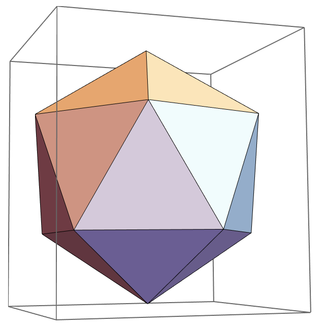
Now imagine that all the edges are replaced by 1-Ohm resistors, what is the equivalent resistor of this network? The way of solving this is by using Kirchhoffs rules.
For every vertex the sum of the current must be 0 (what goes in must go out, otherwise it would accumulate at that vertex). For every edge I can relate the voltages at the ends of the edges (vertices).
V[a] - V[b] = i[a,b] r[a,b]
Since I presume all the resistors to be 1 ohm, this reduces the equation to:
V[a] - V[b] = i[a,b]
where we assume that V is in Volts and i in Amperes (i.e. both in derived SI units without prefixes). By applying a 1 volt difference between opposite ends and figure out how much current will flow we can calculate the equivalent resistance as 1/current.
I programmed this elaborate function to do all of that for me given a polyhedron:
ClearAll[EquivalentResistance,EquivalentResistanceHelper]
EquivalentResistance::invalidstartstop="Start and Stop should be distinct integers between 1 and `1` (inclusive)";
EquivalentResistance[poly_String]:=EquivalentResistance[poly,All]
EquivalentResistance[poly_String,Max]:=Block[{edges,dm,beginend},
    edges=PolyhedronData[poly,"EdgeIndices"];
    dm=DistanceMatrix[PolyhedronData[poly,"VertexCoordinates"]//N];
    beginend=FirstPosition[dm,Max[dm],{2}];
    Dataset[EquivalentResistanceHelper[poly,beginend]]
]
EquivalentResistance[poly_String,All]:=Block[{startsends},
    startsends=Subsets[Union@@PolyhedronData[poly,"EdgeIndices"],{2}];
    Dataset[Association[Thread[startsends->(EquivalentResistanceHelper[poly,#]&/@startsends)]]]
]
EquivalentResistance[poly_String,start_Integer]:=Block[{other},
    other=DeleteCases[Union@@PolyhedronData[poly,"EdgeIndices"],start];
    EquivalentResistance[poly,Thread[{start,other}]]
]
EquivalentResistance[poly_String,startsends:{{_,_}..}]:=Dataset[Association[Thread[startsends->(EquivalentResistanceHelper[poly,#]&/@startsends)]]]
EquivalentResistance[poly_String,{start_Integer,stop_Integer}]:=Dataset[EquivalentResistanceHelper[poly,{start,stop}]]
EquivalentResistanceHelper[poly_String,{start_Integer,stop_Integer}]:=Block[{resistors,edges,inout,begin,end,beginend,vertices,currentrulesin,currentrulesout,currentrules,voltrules,equations,variables,sols,totalcurrent,graphout,eqout,fullsolout,resout,i,V},
    resistors=edges=PolyhedronData[poly,"EdgeIndices"];
    If[1<=start<=Max[edges]\[And]1<=stop<=Max[edges]\[And]start=!=stop,
        {begin,end}=beginend={start,stop};
        edges=Join[edges,inout={{0,begin},{end,Max[edges]+1}}];
        {begin,end}=beginend={0,Max[edges]};
        graphout=HighlightGraph[Graph[UndirectedEdge@@@edges,VertexLabels->"Name",PlotRangePadding->Scaled[.15]],beginend~Join~(Style[#,Red]&/@(UndirectedEdge@@@resistors))];

        vertices=DeleteCases[Union@@edges,Alternatives@@beginend];
        currentrulesout=Table[Select[edges,First[#]==v&],{v,vertices}];
        currentrulesin=Table[Select[edges,Last[#]==v&],{v,vertices}];
        currentrulesin=Total/@Apply[i,currentrulesin,{2}];
        currentrulesout=Total/@Apply[i,currentrulesout,{2}];
        currentrules=Thread[currentrulesin-currentrulesout==0];

        voltrules=Join[V[#1]-V[#2]==i[#1,#2]&@@@edges[[;;-3]],V[#1]==V[#2]&@@@edges[[-2;;]],{V[begin]==1,V[end]==0}];

        equations=Join[voltrules,currentrules];
        variables=DeleteDuplicates[Cases[equations,i[_,_]|V[_],\[Infinity]]];
        sols=Sort@Solve[equations,variables][[1]];

        totalcurrent=i[0,start]/.sols;
        <|"Polyhedron"->poly,"Graph"->graphout,"Start"->start,"Stop"->stop,"Equations"->equations,"Solutions"->sols,"EquivalentResistance"->1/totalcurrent|>
    ,
        Message[EquivalentResistance::invalidstartstop,Max[edges]];
        Abort[]
    ]
]
Two-vertex specification
So how do we call this function? Well, there are several ways:
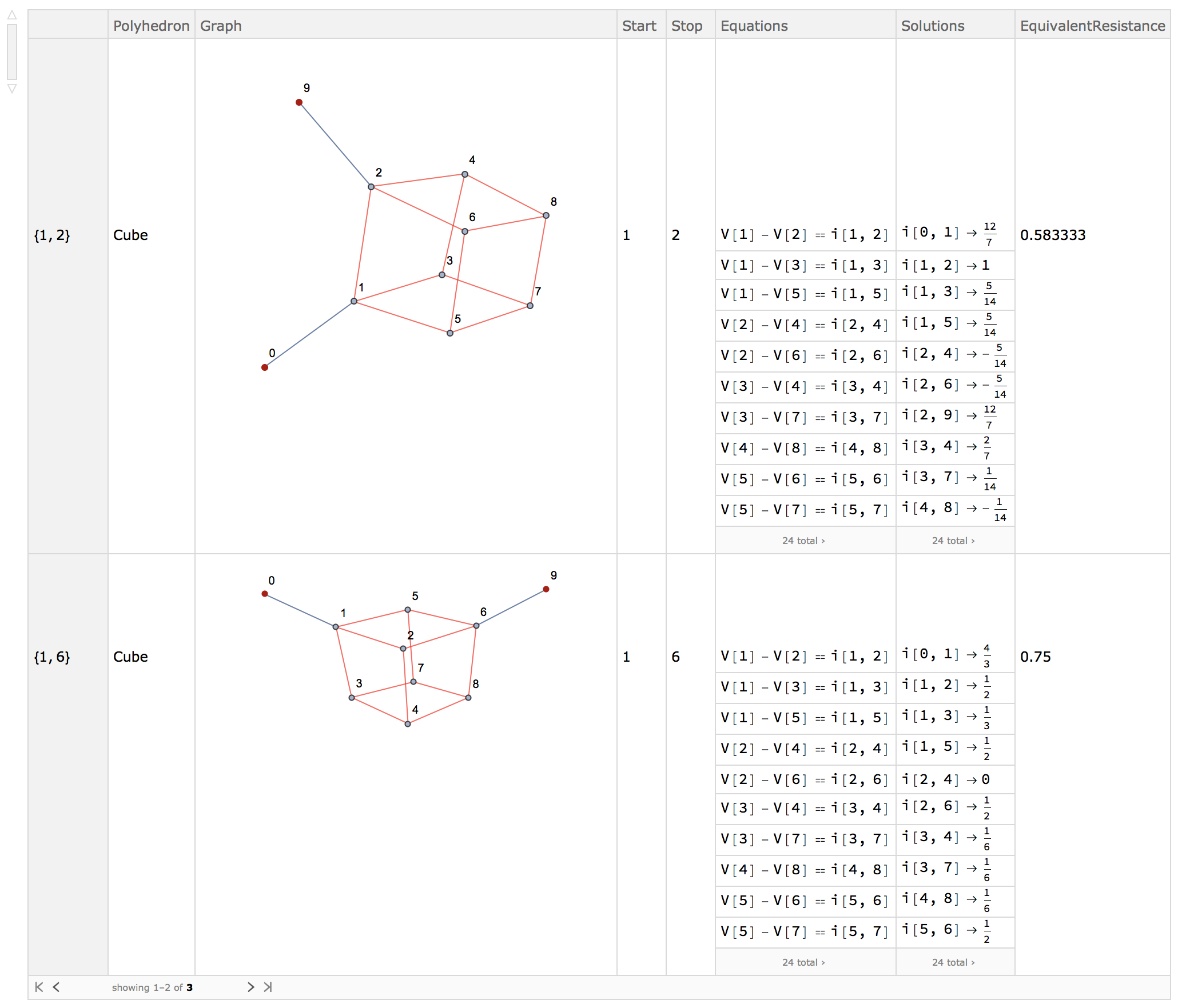
EquivalentResistance["Cube", {1, 2}]
This will give use the equivalent resistance between vertex 1 and 2 of a cube-network of resistors. It gives back a dataset:
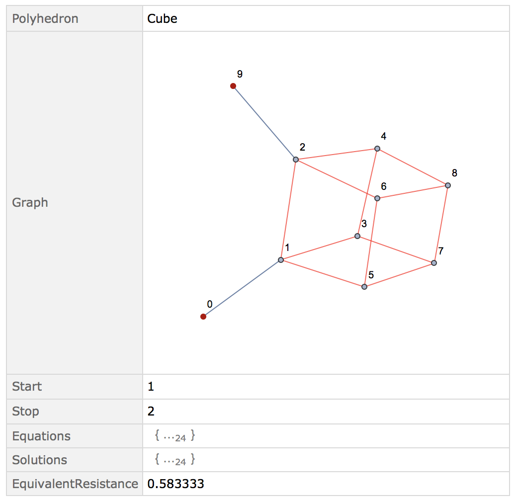
Where the red-edges are 1-ohm resistors and the blue lines are our test-leads with no resistance. You can also see the equations and solutions to those equations:
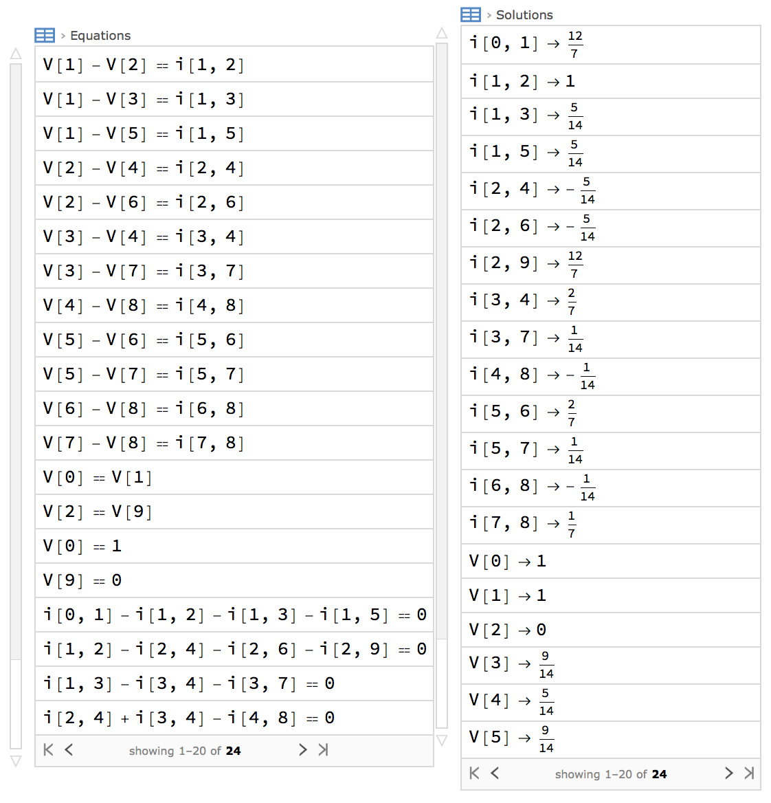
with as many equations as solutions as it should.
Opposite ends
In addition, one can query the function like:
EquivalentResistance["Cube", Max]
which will find two 'opposite' ends of the cube, and calculate the resistance accordingly:
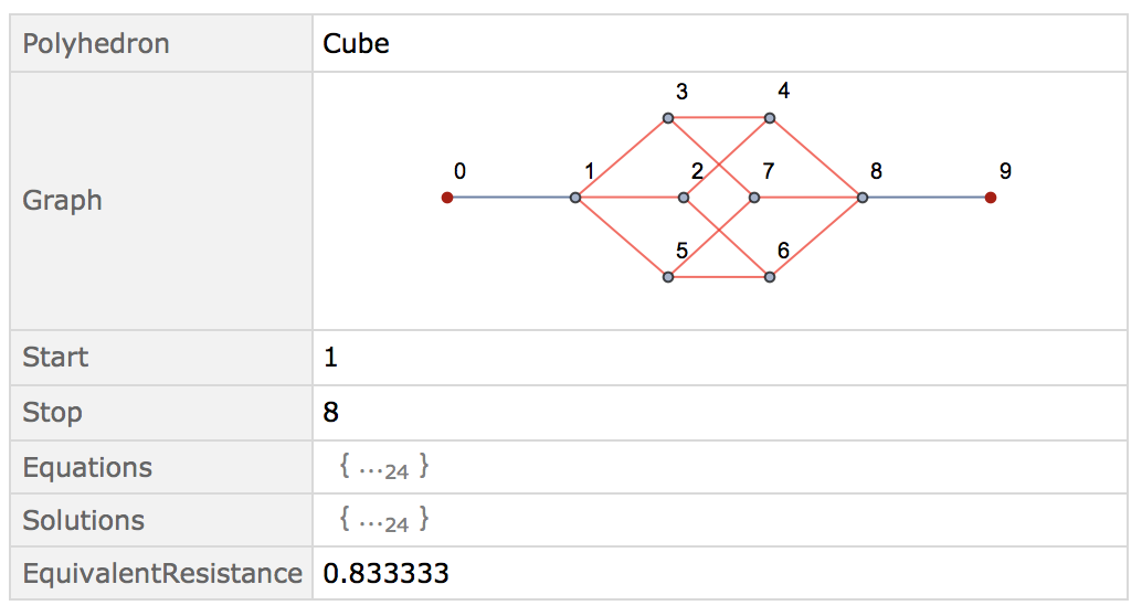
This is the classical problem many of us have solved in school (5/6 Ohm).
Multiple two-vertex specifications
One can also supply multiple pairs:
EquivalentResistance["Cube", {{1, 2}, {1, 6}, {1, 8}}]
giving a more elaborate dataset back:
Start vertex only
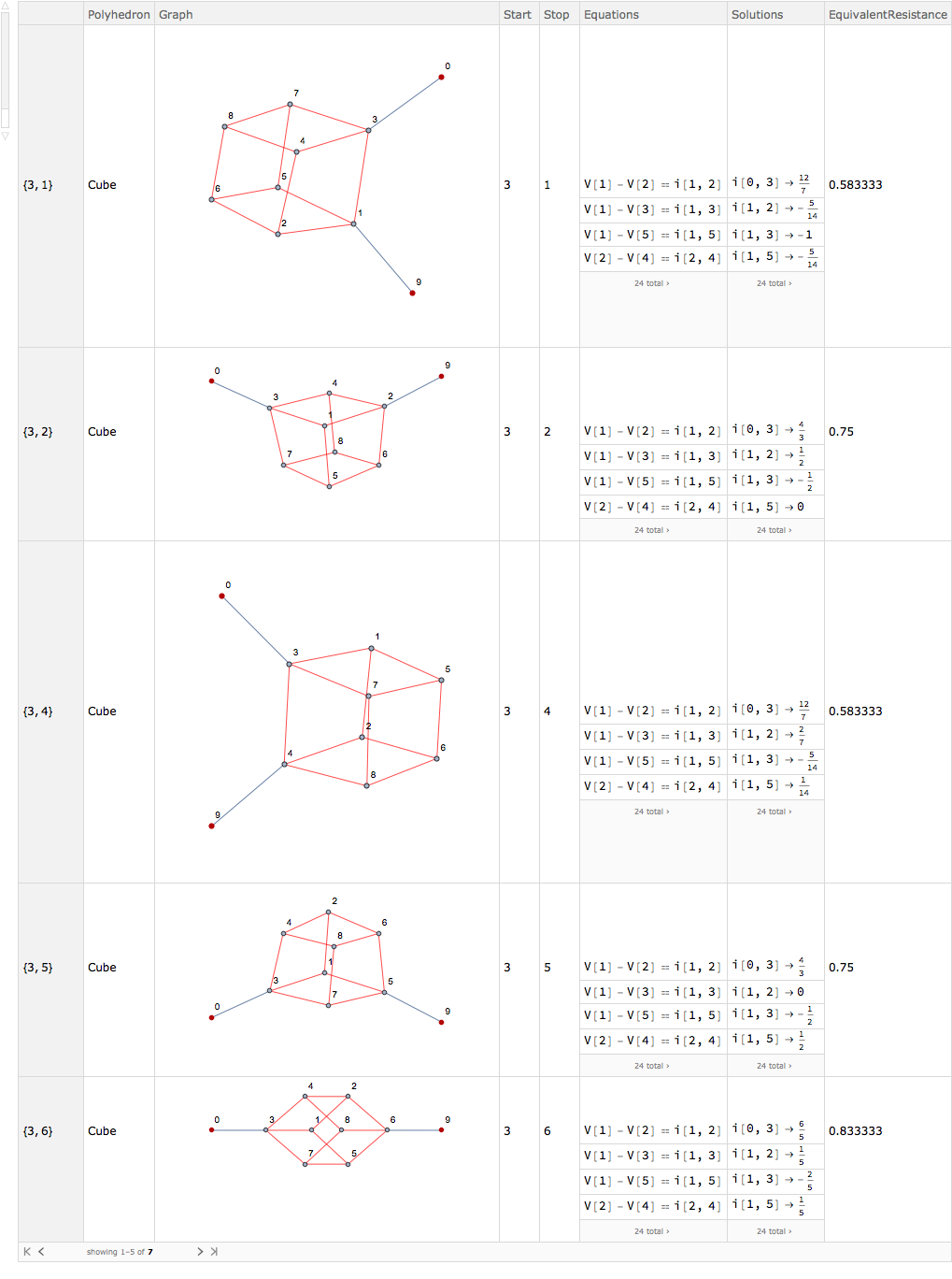
If one supplies only the starting point, it will find the resistance for all the other vertices:
EquivalentResistance["Cube", 3]
in this case it will find all the resistance with starting point 3:
All
Lastly one can specify All (or nothing)
EquivalentResistance["Cube", All] (* same as EquivalentResistance["Cube"] *)
to get a dataset with all possible combinations: 28 cases for a cube (8 edges: Pochhammer[7, 2]/2=28).
Solve original problem
Let's calculate the equivalent resistance for opposite points for all the platonic solids:
Dataset[Normal[EquivalentResistance[#,Max][{"Polyhedron","EquivalentResistance"}]]&/@PolyhedronData["Platonic"]]
giving:
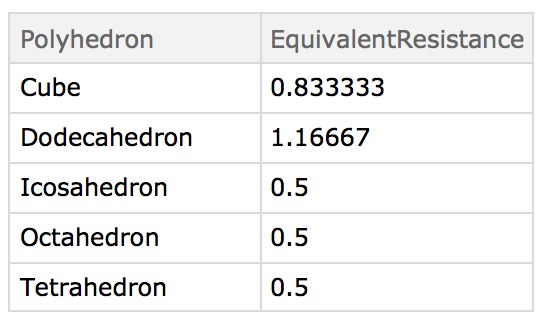
Note that dataset shows numerical approximations of the actual values. The values are actually exact:
Values /@ Normal[%]
giving:
{{Cube,5/6},{Dodecahedron,7/6},{Icosahedron,1/2},{Octahedron,1/2},{Tetrahedron,1/2}}
Other examples
It also works (fast) with larger networks; say a bucky-ball shape:
EquivalentResistance["TruncatedIcosahedron", Max]
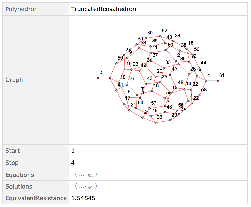
We can also make a table for all the non-compound polyhedrons what the equivalent resistances are:
alldata={#,EquivalentResistance[#,Max]["EquivalentResistance"]}&/@Select[Complement[PolyhedronData[],PolyhedronData["Compound"]],StringQ];
SortBy[Append[#,N[Last[#]]]&/@alldata,Last]//Grid

Some observations: some have an equivalent resistance smaller than 1, others bigger than 1. Somehow I would've expected that all would be smaller than 1 (there are always multiple paths to the ends). Also note that one gets very elaborate fractions for the more complex polyhedrons!
Conclusion
I hope you like this short exploration. One can easily extend this to arbitrary networks with arbitrary resistors. The methodology is the same: set up all the 'current rules', set up 'voltage rules', and some boundary conditions and solve it using Solve.