Hi Dan.
First, let's get a MeshRegion. We could use Import, but here I'm just going to use something from ExampleData.
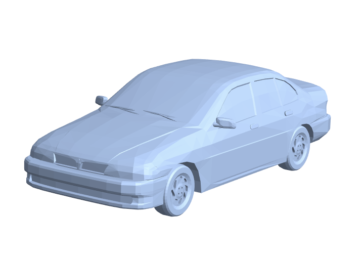
r = DiscretizeGraphics[ExampleData[{"Geometry3D", "SedanCar"}]]
Next, it is easy to find the center of mass of this shape (assuming it is of uniform density). We can just use RegionCentroid.
In[]:= RegionCentroid[r]
Out[]= {-1.36011, 1.87744, 21.4279}
I believe that the axis around which this has the lowest moment of inertia is the eigenvector of the moment of inertia matrix with the lowest associated eigenvalue. We can compute that pretty easily, taking advantage of the fact that, according to its documentation page, "Eigenvectors with numeric eigenvalues are sorted in order of decreasing absolute value of their eigenvalues."
In[]:= Last[Eigenvectors[MomentOfInertia[r]]]
Out[]= {0.00163806, -0.999214, -0.0396081}
That should be the axis with the lowest moment of inertia. We can visualize all of this just to see if it is plausible.
Graphics3D[{
  EdgeForm[None], Opacity[0.2],
  MeshPrimitives[r, 2],
  Opacity[1], Thick, Red,
  InfiniteLine[RegionCentroid[r], Last[Eigenvectors[MomentOfInertia[r]]]],
  Blue, PointSize[Large],
  Point[RegionCentroid[r]]}]
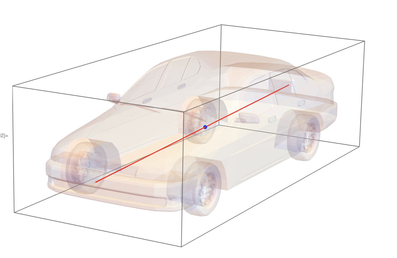
That looks plausible to me!
I hope that helps!


