G-Code contains no information about the part dimensions, and very little about the shape of the cutting tool. Essentially it just refers to a tool table where it retrieves the tool radius and axial offset (for mills). For end mills and ball nose cutters this is enough, but for more complicated tools, their shapes must be stored somewhere else. A bigger challenge is that G-Code is a full programming language, so you can't just translate arbitrary G-Code into Mathematica Graphics3D commands. You would in the general case have to write a G-Code interpreter that would run the code. Since G-Code can invoke arbitrary code (like unix scripts) handling all that could be tricky. So a full G-Code interpreter would be a challenging student project - maybe requiring a small team. If the G-Code contains only G0 or G1 moves, and no fancy stuff, then a simple parse of the G-Code will extract the tool path, and then you would be on your way to getting an STL file. Here is a trivial example, probably of how NOT to do this, since the result is rather rough.
Here an end mill makes a single pass through a rectangular part. The tool path is generated here, not read from a G-Code file. This example shows that RegionPlot3D is a possible starting point for building the STL file. Here we are, in effect doing "plunge milling", so the cut surface is rough. I think this overall approach is called CSG (constructive solid geometry).
Clear[part, path, tool, swarf];

n = 100; (* the number of plot points used by RegionPlot3D in all 3 \
directions *)
stepsize = .01; (* The tool moves in a finite # of \
steps, and this is the distance per step *)

part[{a_, b_, c_}, {c1_, c2_,
   c3_}] := ((0 < #1 - c1 < a) && (0 < #2 - c2 < b) && (0 < #3 - c3 <
      c)) &; (* the geometry of the part, a brick of sides {a,b,c} \
centered at {c1,c2,c3} *)

path = Table[{x, x, 0.1}, {x, 0, 1,
   stepsize}]; (* the path of the center of the bottom of the tool *)
\

tool[{radius_, length_}, {c1_, c2_,
   c3_}] := ((0 < (#1 - c1)^2 + (#2 - c2)^2 <
      radius^2) && (0 < #3 - c3 < length)) &;
(* The cutting tool is an end mill - a cylinder aligned with the z \
axis, the center is located at {c1,c2,c3}. *)

swarf = Not[
      tool[{.05, .5}, #][u, v, w] ] &[First[path ]];
len = Length[path];
i = 0;
While[i <= len - 1, i++; swarf = swarf && Not[
       tool[{.05, .5}, #][u, v, w] ] &  [
   path[[i]]]]; (* the region removed by the tool *)

Show[Graphics3D[{Thickness[.01], Blue, Line[path]}], RegionPlot3D[
  tool[{.05, .5}, {0, 0, .1}][u, v, w]
   ||
    part[{.5, .5, .2}, {.2, .2, 0}][u, v, w], {u, -.2,
   1}, {v, -.2, 1},
  {w, 0, 1}, PlotPoints -> {n, n, n},
  Mesh -> None,
  BoxRatios ->
   Automatic] ](* show the tool, the part and tool path *)

img = RegionPlot3D[
   part[{.5, .5, .2}, {.2, .2, 0}][u, v, w]
   &&
   swarf  , {u, -.2, 1}, {v, -.2, 1},
  {w, 0, 1}, PlotPoints -> {n, n, n},
  Mesh -> None, Boxed -> False, Axes -> False,
  BoxRatios ->
   Automatic]; (* produce the graphic of the milled part *)

Export["test.STL", img];
Import["test.STL"]  (* show the STL file of the milled part *)
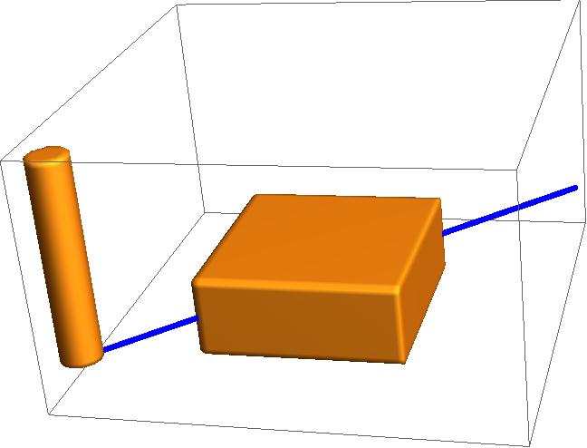
Fig 1 shows a cylinder representing the end mill, the uncut part, and the blue line is the tool path.
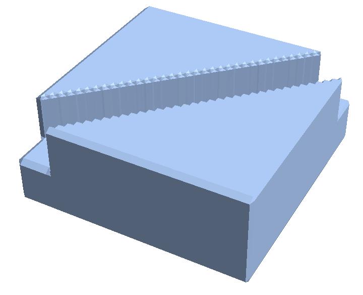
Fig 2 shows we can use Export to convert the Graphics of the milled part from RegionPlot3D into STL.
The result can be improved by increasing the PlotPoints option in RegionPlot3D, but fundamentally this approach is poor since we are not modelling a continuous cut. A possible next level of refinement might be to wrap something like Tube around the path and intersect that with the part, where the Tube would be tweaked to represent the tool cross section.


