Hardware Description Language
The hardware description language is at the register transfer level. This means that register inputs are functions of register outputs and circuit inputs and that in each cycle all register inputs are transferred to the respective outputs simultaneously. All registers have a common implicit transfer clock. Registers are represented by the function d[input,InitialValue:False] which must be the value set to a variable. It is this variable that holds the registers state. A hardware description is a Module[{vars},body] where vars are used to connect registers through expressions. The statement order is unimportant. Here is a 2 bit counter.
Module[{s1,s2},
s1=d[!s1];
s2=d[Xor[s1,s2]];
out[s1];out[s2]]]
The two other language functions are in and out which serve to get data in and out of the simulation. The language also supports Wolfram functions with internal variables, ds, ins and outs that connect through function arguments or returned values.
dff[din,enable,init_:False] overloads = to collect all the d functions into the Association ds used in makeModel. dff is like the more fundamental d except it only transfers when enable is True.
Set[qD_, dff[din_, enable_, init_: False]] ^:=  AssociateTo[ds, qD -> d[If[enable, din, qD], init]]

d[dIn_, init_: False] := dff[dIn, True, init]
first and rest1 are similar to First and Rest but when their arguments are not lists, they don't message and they remain unevaluated. This is used to delay evaluation in the function in. rest1 leaves the last item in the list.
first[{x_, ___}] := x

rest1[{_ : Null, r__}] := {r}
in invokes a d function with value top of stack, popped when pop is True. The last item is not removed from the stack.
in[pop_, stack_] := Module[{l}, l = d[If[pop, rest1@l, l], stack]; first@l]
out makes a Association of expressions to be evaluated in each context and to be returned by step.
out[name_: "noName", sig_] :=AppendTo[os, If[name == "noName", ToString@Unevaluated@sig, name] -> sig]
Simulator
The simulator has 2 parts.
1) makeModel takes a hardware description and returns a function which updates the states and returns an Association of outputs each time it is called. 2) step calls this function count times and returns a DataSet with the expressions from the out functions evaluated at each step.
A function is returned by makeModel. Each time the function is called, the states are updated in parallel to the values of the expressions nexts and outputs are evaluated in the current context of states and returned.
SetAttributes[makeModel, HoldAll];
makeModel[hardwareDescription_] :=
    Block[{ds = <||>, os = <||>},
        hardwareDescription;
         Module[{cycle = 1},
             With[{
                 states = Keys@ds,
                 nexts = Values@ds /. d[n_, _] -> n,
                 outputs = os},
               states = Values@ds /. d[_, init_] -> init;
               With[{result = Evaluate /@ outputs},
                  states = nexts;
                  ToString@cycle++ -> result] &]]]
step returns a Dataset with the Association derived from the out functions evaluated in the context of count state assignments.
step[m_, count_] := Dataset@Association@Table [m[], count]
Devices
Devices are functions in which one or more parameters are set in the function. I have chosen to use the Mathematica convention to the device output the first parameter. Symbols or lists of symbols are used to connect devices thus avoiding the use of Set. Set has the property HoldFirst which makes the setting of lists awkward as symbols representing lists must be evaluated before they are set. Device parameters can also be lists that contain both input and output signals which is useful for implementing busses.
Devices based hardware descriptions correspond to a schematic or netlist. Devices could also be augmented to generate net lists and parts lists.
In[10]:= makeDevice[name_, fn_] := (SetAttributes[name, {Listable}];
  name[out_, ins__] := (out = fn[ins]); "pass")
make a bunch of logic devices
In[11]:= makeDevice @@@ {{notDv, Not}, {andDv, And}, {orDv, Or}, {xorDv,Xor}, {majorityDv, Majority}, {nandDv, Nand},
    {norDv, Nor}, {muxDv,If[#3, #2, #1] &}, {dDv, d}, {dffDv, dff}}

Out[11]= {"pass", "pass", "pass", "pass", "pass", "pass", "pass", "pass", "pass","pass"}

In[12]:= inDv[outD_, en_, data_] := outD = in[en, data]
Examples
Test the elements of the hardware description language.
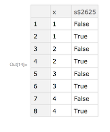
In[13]:= hdlTest = makeModel[
  Module[{s, x},
       s = d[! s];
       x = in[s, {1, 2, 3, 4}];
       out["x", x]; out[s]]]

Out[13]= With[{result$ = Evaluate /@ <|"x" -> first[l$2626], "s$2625" -> s$2625|>},
 {s$2625,  l$2626} = {! s$2625, If[s$2625, rest1[l$2626], l$2626]};
 ToString[cycle$2627++] -> result$] &

In[14]:= step[hdlTest, 8]
A device level model with no top level assignments. The description is a directed graph.
In[16]:= DevideBy3 = makeModel[
    Module[
       {s1, s2, s3},
       out["count1", s1];
       dDv[s2, s1, False];
       nandDv[s3, s1, s2];
       dDv[s1, s3, False];
       out["count2", s2]]]

Out[16]= With[{result$ =
    Evaluate /@ <|"count1" -> s1$3118, "count2" -> s2$3118|>},
    {s2$3118, s1$3118} = {s1$3118, s1$3118 \[Nand] s2$3118};
    ToString[cycle$3119++] -> result$] &

In[17]:= step[DevideBy3, 7]
O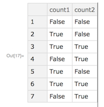
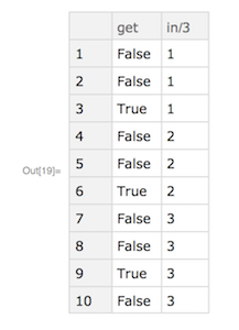
The input arguments to devices may be expressions.
In[18]:= MixedTest = makeModel[Module[
   {s1, s2, s3},
   dDv[s2, s1, False];
   dDv[s1, Nand[s1 s2], False];
   inDv[s3, s1 && s2, Range[3]];
   out["get", s1 && s2];
   out["in/3", s3]]]

Out[18]= With[{result$ =
    Evaluate /@ <|"get" -> s1$3262 && s2$3262,  "in/3" -> first[l$3263]|>},
    {s2$3262, s1$3262, l$3263} = {s1$3262,Nand[s1$3262, s2$3262], If[s1$3262 && s2$3262, rest1[l$3263], l$3263]};
    ToString[cycle$3264++] -> result$] &

In[19]:= step[MixedTest, 10]
 Out[19]= Dataset[ <> ]
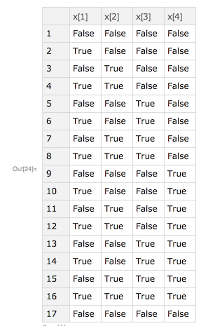
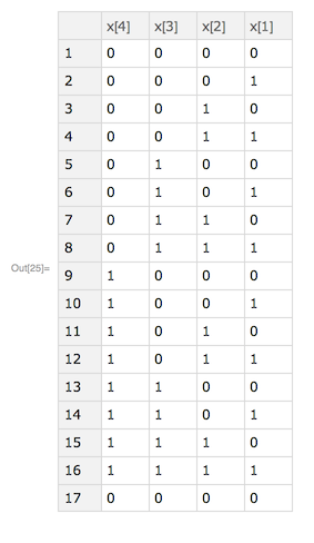
This is an n bit binary counter. The hardware description uses devices with lists of symbols specified by length. The Wolfram language constructs facilitates parameterized devices. This counter uses a toggle flip-flop which toggles when enable is True. enable is True when all when countD is True for all less significant bits.
In[20]:= SetAttributes[tffDv, Listable];
tffDv[oD_, enable_, init_: False] := dffDv[oD, ! oD, enable, init]

In[22]:= counterDv[carryOut_, countD_, carryIn_, length_] :=
     Module[{cy, carry},
         carry = Flatten@{carryIn, Array[cy, length - 1, 2], carryOut};
         andDv[carry[[2 ;;]], countD, carry[[;; -2]]];
         tffDv[countD, carry[[;; -2]]]]

In[23]:= counter4Bit = makeModel[
   Module[{carryOut, count, x},
       count = Array[x, 4];
       counterDv[carryOut, count, True, 4];
       out["x[1]", x[1]]; out["x[2]", x[2]]; out["x[3]", x[3]]; out["x[4]", x[4]]]]

Out[23]= With[{result$ =
    Evaluate /@ <|"x[1]" -> x$3407[1], "x[2]" -> x$3407[2],   "x[3]" -> x$3407[3], "x[4]" -> x$3407[4]|>},
    {x$3407[1], x$3407[2],  x$3407[3], x$3407[4]} =
    {! x$3407[1],  If[x$3407[1], ! x$3407[2], x$3407[2]],  If[x$3407[2] && x$3407[1], ! x$3407[3], x$3407[3]],
        If[x$3407[3] && x$3407[2] && x$3407[1], ! x$3407[4], x$3407[4]]};
     ToString[cycle$3409++] -> result$] &

In[24]:= result4bit = step[counter4Bit, 17]
Reformat to binary
In[25]:= result4bit[All, Reverse] /. {False -> 0, True -> 1}
 Out[25]= Dataset[ <> ]
 Attachments:


