The project
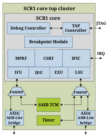
We connected Wolfram Mathematica with SCR1 microcontroller core. For this purpose, we developed a driver for SCR1 based on the Wolfram Device Framework. In our project SCR1 is not a hardware device but an RTL code of processor written in SystemVerilog.
A chip design workflow is a complicated multistage process. At the design stage, engineers describe their solutions with the terminology of the register-transfer level (RTL) using RTL languages such as SystemVerilog. At the verification stage, they have to prove that the design is correct and this is the most complex phase of development. Wolfram Mathematica can help in verification providing comprehensive analytical and visualisation features.
In the project, we used SCR1 as an example of an RTL code because SCR1 is an open-source microcontroller core which is a RISC-V compatible processor. RISC-V is a computer architecture which is open too. The source files of SCR1 can be found at http://github.com/syntacore/scr1. We present a solution where we can substitute SCR1 with any other RTL design. So our project is extendable, and we may say that we built a workflow involving Wolfram Mathematica. The project aims to demonstrate a potential application for Wolfram Mathematica in the semiconductor industry.
All code is posted on GitHub: https://github.com/ckorikov/wolframrussianhack18scr1
What it can do
The Wolfram Device Framework creates symbolic objects that represent external devices. In our case, this is the SCR1 processor. It is the frontend of our system. A description of the backend is in the next section.
SetDirectory[NotebookDirectory[]];
Needs["SCR1Device`"];
device = DeviceOpen["SCR1"]
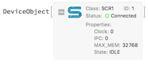
The SCR1 symbolic object has properties and three groups of methods read, write and execute. In our project, users can interact with general purpose registers and memory of the SCR1. For this demonstration we additionally provided access to some wires such as a memory data bus and the branching logic in the processor pipeline. Examples are below.
Properties. There are 4 properties of the SCR1 symbolic object:
State,Clock,IPC (instruction program counter),MAX_MEM (maximal memory).
The state property reflects a state of the processor and can have the following values: IDLE, WORK and FINISHED. This property is WORK after reset. When a program completes, the state transitions to FINISHED. The clock contains the number of ticks of a clock signal from a simulation start. The IPC shows a value of the IPC register. This value is an address of a currently executed instruction. MAX_MEM is a size of memory in bytes. These properties are read-only and can be accessed by the name of the property as follows.
device["MAX_MEM"]
32768
Reading methods. The general format of these commands is DeviceRead[device, "CMD"]. Instead of CMD, use one of the following commands.
STATE: read the state of SCR1 (State, Finished, Clock, IPC).REGS: read the list of register values (from 1 to 32).MEM: read the list of bytes from memory.BRANCH: read the state of branching logic (IPC, Jump, Branch_taken, Branch_not_taken, JB_addr).DBUS: read the memory data bus (Address, Bytes).
Writing methods. The general format of these commands is DeviceWrite[device, "CMD"]. Instead of CMD, use one of the following commands.
REGS: modify a value of a register.MEM: modify a value of a memory cell.
Execution methods. The general format of these commands is DeviceExecute[device, "CMD"]. Instead of CMD, use one of the following commands.
RESET: reset the processor.HARD_RESET: reset the processor and internal counters of the simulator (such as simulation time and the clock counter).LOAD: load a program to memory and reset the processor.STEP: perform one tick of the clock signal.RUN: make steps until the end of the program.RUN_UNTIL_IPC: make steps until a specific IPC value.TRACE_IPC: execute RUN command and return a list of IPC values.
Basic examples
1. Program loading, soft and hard resets
To load a program execute the following command. An argument is a path to the program file.
DeviceExecute[device,
  "LOAD",
  "./scr1_programs/dhrystone21.bin"
  ];
To reset the processor use RESET and HARD_RESET commands. Hard reset is soft reset + simulator cleanup.
2. Read data about SCR1
These are examples of reading commands output.
Dataset@DeviceRead[device, "STATE"]
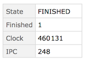
Here, Finished is a flag which is 1 if SCR1 reaches the end of the program otherwise is 0. Other output values are the same as symbolic object properties.
Dataset@DeviceRead[device, "BRANCH"]
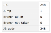
Structures like ifthenelse create branches in code execution flow. The BRANCH command returns information about the current branching state. Jump, Branch_taken, Branch_not_taken are flags. They are 1 if the instruction is jump or a branch has been detected, and it has been taken or not taken, respectively. JB_addr is an address of the next instruction if jump or branch has occurred.
Dataset@DeviceRead[device, "DBUS"]

Data and program instructions are located in memory. A processor fetches them through a memory bus. DBUS returns an address of the memory cell and the size of the requested data in bytes.
Dataset@MapIndexed[
  {#2[[1]], BaseForm[#1, 16], BaseForm[#1, 2]} &,
  DeviceRead[device, "REGS"]
  ]
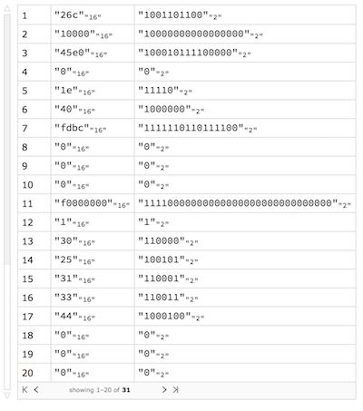
Any computations on the processor involve registers. We can read their values. This is an example of reading values of the register in binary and hexadecimal forms.
BaseForm[#, 16] &@DeviceRead[device, {"MEM", 512, 100}]

Also, we can read the contents of the memory. The first argument is the address of a cell. The second is the number of cells.
3. Write data to memory and registers
Write the value to the memory and check it.
DeviceWrite[device, {"MEM", 10000, 10}];
DeviceRead[device, {"MEM", 10000, 1}]
{10}
The first argument is the address of a memory cell. The second one is the value.
DeviceWrite[device, {"REGS", 5, 30}];
DeviceRead[device, "REGS"]
{0, 0, 0, 0, 30, 0, 0, 0, 0, 0, 0, 0, 0, 0, 0, 0, 0, 0, 0, 0, 0, 0, 0, 0, 0, 0, 0, 0, 0, 0, 0}
The first argument is a register index. The second one is the value.
4. Program execution on SCR1
There are several functions which start the program flow. The first is STEP. This function produces one clock of the simulator and returns the number of clocks. This function works until the end of the program. After that, the core needs to be reset. We can use the NEXT_IPC function if we would like to run SCR1 until the next instruction occurs. The function returns a value of new IPC. Additionally, SCR1 may be run until a particular IPC value is encountered with the RUN_UNTIL_IPC command. If we would like to launch SCR1 before the program ends, we can use RUN function. If the program prints something to display, it is redirected to src1_output.txt file.
Framed@Import["src1_output.txt"]
This is an example of the output.
HELL0 SCR1

Dhrystone Benchmark, Version 2.1 (Language: C)

Program compiled without 'register' attribute

Execution starts, 500 runs through Dhrystone
Execution ends

Final values of the variables used in the benchmark:

Int_Glob:            5
        should be:   5
Bool_Glob:           1
        should be:   1
Ch_1_Glob:           A
        should be:   A
Ch_2_Glob:           B
        should be:   B
Arr_1_Glob[8]:       7
        should be:   7
Arr_2_Glob[8][11]:    510
        should be:   Number_Of_Runs + 10
Ptr_Glob->
  Ptr_Comp:          15412
        should be:   (implementation-dependent)
  Discr:             0
        should be:   0
  Enum_Comp:         2
        should be:   2
  Int_Comp:          17
        should be:   17
  Str_Comp:          DHRYSTONE PROGRAM, SOME STRING
        should be:   DHRYSTONE PROGRAM, SOME STRING
Next_Ptr_Glob->
  Ptr_Comp:          15412
        should be:   (implementation-dependent), same as above
  Discr:             0
        should be:   0
  Enum_Comp:         1
        should be:   1
  Int_Comp:          18
        should be:   18
  Str_Comp:          DHRYSTONE PROGRAM, SOME STRING
        should be:   DHRYSTONE PROGRAM, SOME STRING
Int_1_Loc:           5
        should be:   5
Int_2_Loc:           13
        should be:   13
Int_3_Loc:           7
        should be:   7
Enum_Loc:            1
        should be:   1
Str_1_Loc:           DHRYSTONE PROGRAM, 1'ST STRING
        should be:   DHRYSTONE PROGRAM, 1'ST STRING
Str_2_Loc:           DHRYSTONE PROGRAM, 2'ND STRING
        should be:   DHRYSTONE PROGRAM, 2'ND STRING

Number_Of_Runs= 500, HZ= 1000000
Time: begin= 15331, end= 165400, diff= 150069
Microseconds for one run through Dhrystone: 300
Dhrystones per Second:                      3331
- tb/scr1_top_tb_axi.sv:314: Verilog $finish
Additional examples
1. Memory maps of programs
In this example, we show a grid of memory maps for programs from the scr1_programs directory. A memory map is a matrix of memory cells where each element is highlighted depending on the value of the cell. 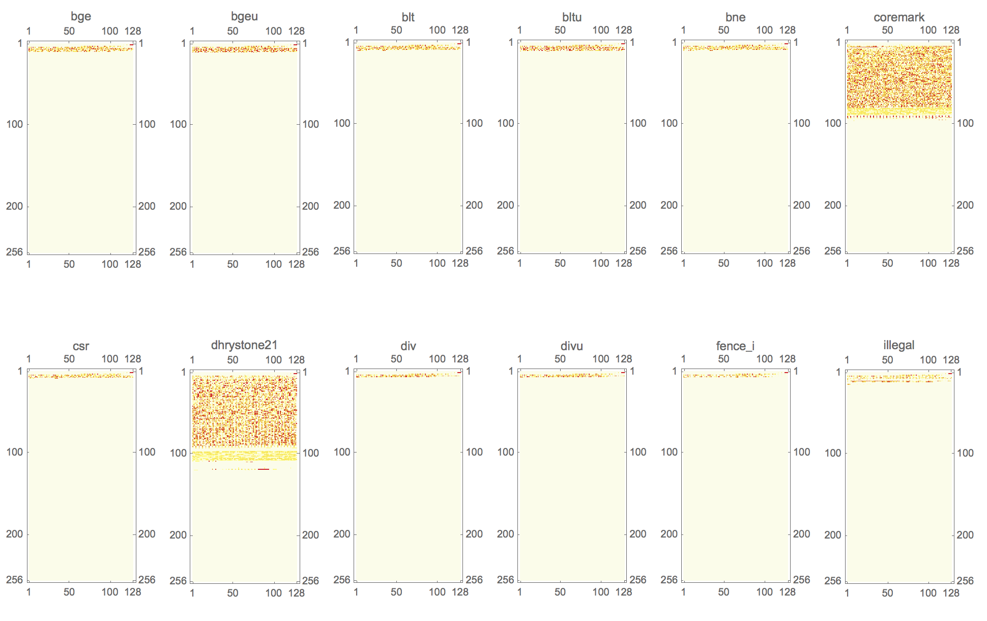
2. Execution graph of programs
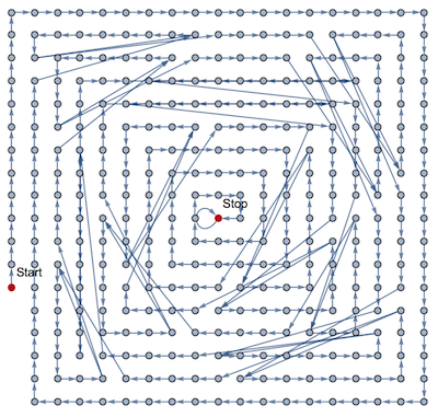
We can visualise the trace of program execution. We used a directed graph whose vertices are instructions which are placed in the order of how they were executed. We can see that using the graph it is easy to find jumps in programs.
3. Call graph
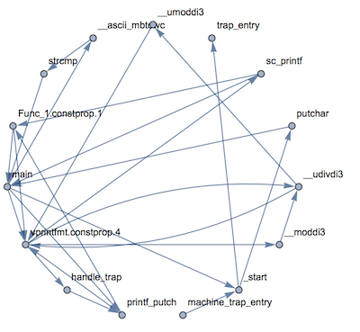
There are assembler dumps in the scr1_programs directory. We use this dumps to map instructions to the names of functions. In this example, we parse assembler files, find ranges of addresses and use them for mapping.
4. Transactions to memory
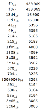
This example shows how to trace data manually with Wolfram Mathematica. Also, we calculate a list of frequent addresses which is accessed by SCR1 for a particular program (dhrystone21).
5. Develop new devices: branch predictor
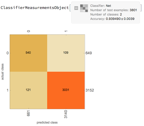
Our solution provides loads of data about the core. Engineers can use this data to design or optimise modules. For instance, we can get information about branching of SCR1 and use this data for developing a branch predictor module.
The purpose of the branch predictor is to improve the flow in the instruction pipeline. Branch predictors play a critical role in achieving high performance in many modern pipelined processors.
Here we use machine learning methods, a neural network, to build a predictor.
How it works
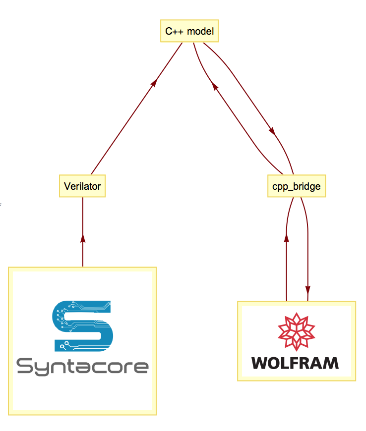
The driver encapsulates lower-level interactions with the SCR1. We cannot use SystemVerilog in Wolfram Mathematica directly. That is why we converted the SCR1 code to C++ code by Verilator software (https://www.veripool.org/wiki/verilator). This program is an open-source Verilog/SystemVerilog simulator. We wrapped generated C++ code with functions to communicate with Wolfram Mathematica through the Wolfram LibraryLink. The full scheme of the project is below.
Conclusions
Over the course of 24 hours our team built a prototype of a hardware verification workflow with the SCR1 microcontroller. We implemented:
- device driver for the SCR1 processor based on the Wolfram Device Framework;
- the C++ bridge between Wolfram Mathematica and generated C++ by Verilator;
- examples of using this system for verification programs and hardware;
- the design of a branch predictor.
Our verification solution provides register and memory access and a step-by-step debugger (in clock or instruction modes). To build a powerful hardware debugger it is necessary to add the feature of making dumps of arbitrary signals for any RTL design. The last is a potential topic for future work.