Hi Nick,
I didn't get your system to work by disconnecting the control loop and connecting the constant to the valve.
I restructured your model slightly, and instead of using a constant pressure I use an ambient with constant properties.
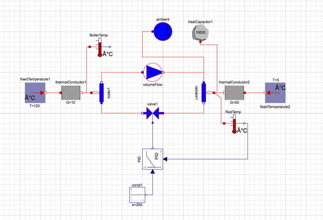
And the model code:
model HouseCH_V2r0
parameter Modelica.SIunits.Temperature TAmb=293 "Ambient Temperature";
parameter Modelica.Thermal.FluidHeatFlow.Media.Medium Water=Modelica.Thermal.FluidHeatFlow.Media.Water() "Cooling medium";
Modelica.Thermal.FluidHeatFlow.Components.HeatedPipe radiator1(dpLaminar=1000, dpNominal=10000, V_flowLaminar=0.0001, V_flowNominal=0.0003, m=1, T0=TAmb, h_g=0, medium=Water) annotation(Placement(visible=true, transformation(origin={40,20}, extent={{-10,10},{10,-10}}, rotation=270)));
Modelica.Thermal.FluidHeatFlow.Components.HeatedPipe boiler1(dpLaminar=1000, dpNominal=10000, m=1, h_g=0, V_flowLaminar=0.0001, V_flowNominal=0.0003, T0=TAmb, medium=Water) annotation(Placement(visible=true, transformation(origin={-60,20}, extent={{10,-10},{-10,10}}, rotation=270)));
Modelica.Thermal.HeatTransfer.Components.ThermalConductor thermalConductor1(G=10) annotation(Placement(visible=true, transformation(origin={-90.0,20.0}, extent={{-10.0,-10.0},{10.0,10.0}}, rotation=0)));
Modelica.Thermal.HeatTransfer.Components.ThermalConductor thermalConductor2(G=20) annotation(Placement(visible=true, transformation(origin={70.0,20.0}, extent={{10.0,-10.0},{-10.0,10.0}}, rotation=0)));
Modelica.Thermal.HeatTransfer.Celsius.FixedTemperature fixedTemperature1(T=120) annotation(Placement(visible=true, transformation(origin={-125.0,20.0}, extent={{-10.0,-10.0},{10.0,10.0}}, rotation=0)));
Modelica.Thermal.HeatTransfer.Celsius.FixedTemperature fixedTemperature2(T=5) annotation(Placement(visible=true, transformation(origin={110.0,20.0}, extent={{-10.0,-10.0},{10.0,10.0}}, rotation=-540)));
Modelica.Thermal.HeatTransfer.Components.HeatCapacitor heatCapacitor1(C=10000) annotation(Placement(visible=true, transformation(origin={36.7477,80.0}, extent={{-10.0,-10.0},{10.0,10.0}}, rotation=0)));
Modelica.Thermal.HeatTransfer.Celsius.TemperatureSensor BoilerTemp annotation(Placement(visible=true, transformation(origin={-61.5702,65.0}, extent={{-10.0,-10.0},{10.0,10.0}}, rotation=0)));
Modelica.Thermal.HeatTransfer.Celsius.TemperatureSensor RadTemp annotation(Placement(visible=true, transformation(origin={70.0,-10.0}, extent={{-10.0,-10.0},{10.0,10.0}}, rotation=0)));
Modelica.Thermal.FluidHeatFlow.Components.Valve valve1(frictionLoss=0, kv0=0, Kv1=0.001, y1=1, T0=TAmb, rho0=996, medium=Water, m=0.1, LinearCharacteristic=true, dp0=100) annotation(Placement(visible=true, transformation(origin={-10.0,0.0}, extent={{-10.0,-10.0},{10.0,10.0}}, rotation=-540)));
Modelica.Blocks.Sources.Constant const1(k=250) annotation(Placement(visible=true, transformation(origin={-25,-107.5}, extent={{-7.5,-7.5},{7.5,7.5}}, rotation=0)));
Modelica.Thermal.FluidHeatFlow.Sources.VolumeFlow volumeFlow(m=1, T0=293, constantVolumeFlow=0.3, medium=Water) annotation(Placement(visible=true, transformation(origin={-10,40}, extent={{-10,-10},{10,10}}, rotation=0)));
Modelica.Thermal.FluidHeatFlow.Sources.Ambient ambient(constantAmbientPressure=1000, constantAmbientTemperature=250, medium=Water) annotation(Placement(visible=true, transformation(origin={0,120}, extent={{-10,-10},{10,10}}, rotation=0)));
Modelica.Blocks.Continuous.LimPID PID(yMax=1, yMin=0.0001, Ti=0.1, Td=0.1, wd=1) annotation(Placement(visible=true, transformation(origin={-10,-45}, extent={{-10,-10},{10,10}}, rotation=90)));
equation
connect(RadTemp.T,PID.u_m) annotation(Line(visible=true, origin={62,-27.5}, points={{18,17.5},{21,17.5},{21,-17.5},{-60,-17.5}}, color={0,0,127}));
connect(PID.u_s,const1.y) annotation(Line(visible=true, origin={-12.25,-90.667}, points={{2.25,33.667},{2.25,-16.833},{-4.5,-16.833}}, color={0,0,127}));
connect(PID.y,valve1.y) annotation(Line(visible=true, origin={-10,-21.5}, points={{0,-12.5},{0,12.5}}, color={0,0,127}));
connect(ambient.flowPort,radiator1.flowPort_a) annotation(Line(visible=true, origin={1.8,94.2}, points={{-11.8,25.8},{-21.8,25.8},{-21.8,-34.2},{38.2,-34.2},{38.2,-64.2}}, color={255,0,0}));
connect(volumeFlow.flowPort_b,radiator1.flowPort_a) annotation(Line(visible=true, origin={26.667,36.667}, points={{-26.667,3.333},{13.333,3.333},{13.333,-6.667}}, color={255,0,0}));
connect(volumeFlow.flowPort_a,boiler1.flowPort_b) annotation(Line(visible=true, origin={-46.667,36.667}, points={{26.667,3.333},{-13.333,3.333},{-13.333,-6.667}}, color={255,0,0}));
connect(thermalConductor1.port_b,BoilerTemp.port) annotation(Line(visible=true, origin={-75.1777,42.5}, points={{-4.8223,-22.5},{0.6074,-22.5},{0.6074,22.5},{3.6074,22.5}}, color={191,0,0}));
connect(radiator1.heatPort,RadTemp.port) annotation(Line(visible=true, origin={56,2.5}, points={{-6,17.5},{1,12.5},{1,-12.5},{4,-12.5}}, color={191,0,0}));
connect(valve1.flowPort_a,radiator1.flowPort_b) annotation(Line(visible=true, origin={26.667,3.333}, points={{-26.667,-3.333},{13.333,-3.333},{13.333,6.667}}, color={255,0,0}));
connect(radiator1.heatPort,heatCapacitor1.port) annotation(Line(visible=true, origin={45.899,48.8}, points={{4.101,-28.8},{7.101,-28.8},{7.101,18.2},{-9.151,18.2},{-9.151,21.2}}, color={191,0,0}));
connect(radiator1.heatPort,thermalConductor2.port_b) annotation(Line(visible=true, origin={55,20}, points={{-5,0},{5,0}}, color={191,0,0}));
connect(valve1.flowPort_b,boiler1.flowPort_a) annotation(Line(visible=true, origin={-46.667,3.333}, points={{26.667,-3.333},{-13.333,-3.333},{-13.333,6.667}}, color={255,0,0}));
connect(thermalConductor1.port_b,boiler1.heatPort) annotation(Line(visible=true, origin={-75,20}, points={{-5,0},{5,0}}, color={191,0,0}));
connect(fixedTemperature2.port,thermalConductor2.port_a) annotation(Line(visible=true, origin={90.0,20.0}, points={{10.0,0.0},{-10.0,0.0}}, color={191,0,0}));
connect(fixedTemperature1.port,thermalConductor1.port_a) annotation(Line(visible=true, origin={-107.5,20.0}, points={{-7.5,0.0},{7.5,0.0}}, color={191,0,0}));
annotation(__Wolfram(totalModelMain=true, totalModelId="8f2f9f71-0467-463a-a9cf-26d163f29057"), experiment(StopTime=10), Icon(coordinateSystem(extent={{-100.0,-100.0},{100.0,100.0}}, preserveAspectRatio=true, initialScale=0.1, grid={10,10}), graphics), Diagram(coordinateSystem(extent={{-210.0,-148.5},{210.0,148.5}}, preserveAspectRatio=true, initialScale=0.1, grid={5,5})));
end HouseCH_V2r0;
In general I like to see examples which have a typical package structure, for a guide to this see this short tutorial/course:
http://www.wolfram.com/training/courses/eng031.html


