A shorter possibility than what I explain below is that the bounding box has a different coordinate system than the XYZ of the graphics (a rotation). So if what follows makes sense, then it is a bug. If what follows does not make sense, then it implies the "camera" view angle has a different coordinate system than the XYZ of the graphics. I'm tending towards the idea that it is a caching bug since when I originally entered this it did as expected, and results only failed after adding code and then removing code or editing code.
If this gets too long, just jump to the question at the end.
Take a very close look at the image following the text of my previous post. Search for "What this produces when Cone is not shown:", and then note the graphic this refers to. The bounding box is centered on {0,0,0}, meaning bounding box and actual coordinate system match for this case (bounding box and graphics should correspond 1:1). Note that this image is from slightly above and to the right of the bounding box center. This seems wrong since the code is from above and left (if they use the same coordinate system...or is my idea of -0.25 being "left" wrong?):
  ViewCenter -> {0, 0, 0},
  ViewPoint -> {-0.25, 0.25, 2},
In that same post with the original graphic, right at the top, I had to add an "EDIT" regarding the view:
EDIT: I noticed that my original view which should be from slightly above and left is now not what I thought it was. View should be from {-0.25,0.25,2} pointed directly at {0,0,0}. For a while the "plane only" demo was viewing this correctly. Now this is viewing from above and right (not left, which it should).
Originally I did see that image was with camera above and left (which is what an X coordinate of -0.25 would do) in terms of the graphics I saw prior to posting. Later on, using that same view point of {-0.25,0.25,2} pointed directly at {0,0,0} in a bounding box which is symmetric about the center of the coordinate system (the coordinate system center of the graphic and bounding box were the same without the cone), the camera view shifted to the positive X direction, and I didn't know why. Basically I had been commenting and uncommenting code to experiment, but upon going back to the original the view perspective never went back to viewing from above and to the left. The view from after having shifted things around when adding the cone was being preserved and did not go back to what it should be. The bounding box seems to mistakenly believe there is still more geometry to show where the cone no longer exists. Even after commenting out the cone the bounding box is being treated as if the cone is still there. The view is being cached for some reason and not refreshed upon edit.
Later on I changed the InfiniteLine to just Line from -1 to 1 along each axis and commented out the cone once more. This was to force bounding box to include -1 to 1 of each axis. This was done as an edit, not as new code. The result was that the view point and center remained to the upper right, not left, even though the bounding box was what I expected.
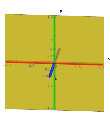
If you were to enter the code for the first time, then the display would be correct. Each time you edit such that bounding box changes, and then revert the edit, the view does not revert as other geometry is edited out. This became true even on new documents. The following should have a view centered on {0,0,0} of both axes and bounding box. The actual camera should be above and left. If you then uncomment the cone, then view should go to the right as the cone extends the total image. Following this, if you recomment the cone, then the view will not go back to the original form as it should (the cone goes away, but the bounding box changes from having added the cone originally does not go away). This seems to be a caching issue. This is what I see, and the view is wrong for an X coordinate of negative 0.25:
Don't know if it matters, but my 11.3 is running on Linux. I'd consider it possible that the cache mechanism differs on different operating systems. However, it looks like there is a simple cache directory mechanism on Linux, so maybe I have to delete the cache each time I edit.
Incidentally, if I run this code with ViewPoint (camera) at {0,0,2}, there is a definite rotation which I do not expect, and once again it says that either the bounding box coordinate system differs from the graphic, or else some bug is getting me (I still have "Show" in because I was expecting to add "Manipulate" later):
Show[
 Graphics3D[
   {
   RGBColor[1, 1, 0, 0.8],
   InfinitePlane [  {  {0, 0, 0}, {1, 0, 0}, {0, 1, 0}  } ],
   (*RGBColor[0.8,0.8,0.8,0.8],
      Cone[ {{1,1,0},{0,0,0}},Sqrt[2]
   ],*)
   {Thickness[0.025], Red, Line[{{-1, 0, 0}, {1, 0, 0}}]},
   {Thickness[0.025], Green, Line[{{0, -1, 0}, {0, 1, 0}}]},
   {Thickness[0.025], Blue, Line[{{0, 0, -1}, {0, 0, 1}}]},
   {PointSize[Large], Black, Point[{0, 0, 0}]}
   },
  Axes -> True,
  AxesLabel -> {
    Style["x", Bold, Black],
    Style["y", Bold, Black],
    Style["z", Bold, Black]
    },
  AxesOrigin -> {0, 0, 0},
  AxesEdge -> {{0, 0}, {0, 0}, {0, 0}},
  Boxed -> True,
  ViewProjection -> "Orthographic",
  ViewCenter -> {0, 0, 0},
  ViewPoint -> {-0.25, 0.25, 2},
  ViewVertical -> {0, 1, 0}
  ]
 ]
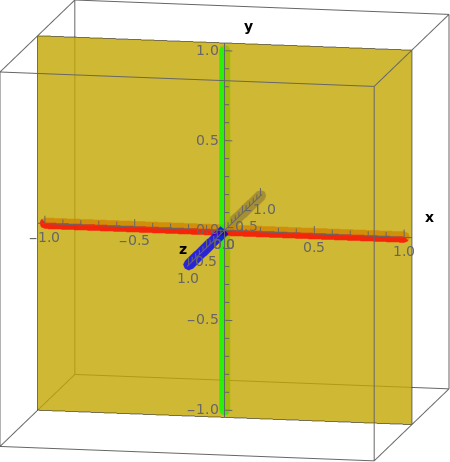
Is this what you get for a view when entering the code I just added? Should bounding box and geometry coordinate systems be the same for this case? Is this last image what I should expect from a view point of {0,0,-2}? Are you using Mathematica under Linux?


