Message Boards Message Boards

Generalizing "rules" and an example of generation of 2D-grid

The fundamental idea of the Wolfram model is having an initial graph $G_0$ together with a rule $r$ telling you how to "update" the graph. So far (unless I have missed something) the rule is of the following form:

  • A "left-hand side" which detects the part of the graph to be updated.
  • A "right-hand side" which tells you what the formerly detected part of the graph should be changed to.

This can be generalized in order to be less restrictive. Instead of considered just one rule, it is possible to define the rule as an ordered set of subrules, which should all be applied in the right order each time the rule is applied. Thinking of rules as being operators on graphs, we could write it as a kind of product: $$r=r_n\cdots r_3r_2r_1,$$ where all the $r_i$ denote the subrules.

A graph (and the left- and right-hand sides of rules) can essentially be thought of as subsets of $\mathbb{N}^2$ (or $\mathbb{Z}^2$ or maybe even $\mathbb{R}^2$ even though the real numbers are probably not suited for this in nature discrete theory). I will come back to this idea later, but for now, it is simply a motivation to use the notation $\{(a,b),(b,c)\}$ instead of the notation $\{\{a,b\},\{b,c\}\}$ when talking about rules. It also seems more readable to me, but this is of course simply a personal opinion. Also, note that everything I mention in this post is easily generalized to hypergraphs.

I will add some more notation in order to make things easier (and one more addition to how we make rules).

  • A new bracket: $[a,b]=(a,b),(b,a).$ This means that the relation between the vertices goes both ways.
  • The notation $\overline{(a,b)}$ in a rule called a negation means that this relation should not exist in order for the rule to be applied. This generalizes the left-hand side of the rule to demands of existence and lag of existence. This notation only makes sense on the left-hand side of a rule.
  • The last notation only makes sense on the right-hand side of a rule. This is used when the rule only adds something new without removing anything, which would usually require writing the entire left-hand side again together with the new relations. In this case, I will simply right a "$+$" to represent the left-hand side (except the negated parts). For example $r: \{(a,b),(b,c)\}\rightarrow \{(a,b),(b,c),(c,d)\}$ is written as $r:\{(a,b),(b,c)\}\rightarrow \{+,(c,d)\}$ and $r: \{(a,b),(b,c),\overline{(c,d)}\}\rightarrow \{(a,b),(b,c),(c,d)\}$ is written as $r:\{(a,b),(b,c),\overline{(c,d)}\}\rightarrow \{+,(c,d)\}$.

I want to motivate all these new definitions by creating an initial condition and a rule which generates a 2D-grid. For simplicity, I will make all relations between vertices go both ways and thus use $[\cdot,\cdot]$. The initial condition is simply a square: $$G_0=\{[1,2],[2,3],[3,4],[4,1]\}$$ The rule is a composition of three subrules $r=r_3r_2r_1$. I will not use letters but numbers in the rules, but this is still to be thought of as "place holders" and not specific vertices. The three rules are:

  • $r_1$: $\{[1,2],[2,3],[3,4],\overline{(2,5)},\overline{(3,6)}\}\rightarrow\{+,[2,5],[5,6],[6,3]\}$. This rule identifies two connected vertices of valency 2. That is, vertices with two edges. It then adds to these two vertices a new square.
  • $r_2$: $\{[1,2],[1,3],[1,4],[4,5],[4,6],[4,7],[5,8],\overline{(1,9)},\overline{(5,10)}\}\rightarrow\{+,[1,9],[10,5]\}$. This rule first identifies a valency 3 vertic, which is connected to a valency 2 vertex through one other vertex of valency 4 (a bit like a stair). It then adds a square to the stair.
  • $r_3$: $\{[1,2],[1,3],[1,4],[4,5],[5,6],[5,7],\overline{(1,8)},\overline{(5,9)}\}\rightarrow\{+,[1,8],[8,5]\}$. This rule does the same as rule $r_2$ except it adds a new square to two valency 3 vertices seperated by one vertex instead of valency 3 and 2 vertices.

enter image description here

enter image description here

enter image description here

Let's see what this rule does to the square. Applying the entire rule means that we should apply $r_1$ first. This rule adds to all four edges a new square giving a "big plus" of squares. Since there are no valency 3 vertices in this graph, applying $r_2$ and $r_3$ changes nothing.

Now apply the rule once more. Firstly, one more square is added above, below, and at both sides of the plus giving a longer plus. Subrule two does nothing again. Subrule three adds a square in each corner of the plus resulting in a diamond shape.

The third time the rule is applied and henceforth, all three subrules matter. The diamond shape will simply keep growing, by first adding squares to the four ends and then all the way around. (Note: I might have made mistakes in the rule since it is all still new to me).

The first three stages of the graph are (blue is $G_0$, black is generated by $r_1$, and red is generated by $r_3$ while $r_2$ is irrelevant in these steps):

enter image description here

Lastly, I want to describe a different kind of initial conditions. One theory for the universe says that it is infinite and always was infinite. We can actually make infinite initial conditions. For example, the graph which is the line of all integers is simply the disjoint union of all succeeding integers and could be taken as an initial condition:

$$\bigsqcup_{n=\infty}^{\infty}(n,n+1)=G_0$$

Representing each side of a rule as subsets of $\mathbb{Z}^2$ could also involve equations. For example:

$$r:\{(x,x+1)\}\rightarrow\{+,(x+1,x)\}$$

This rule would replace all $(\cdot,\cdot)$-brackets with $[\cdot,\cdot]$-brackets if applied on the $G_0$ defined above. I think infinite initial conditions is both interesting and important to consider. They are, however, more complicated to compute and visualize.

POSTED BY: Malthe Andersen
15 Replies

Thank you Johann-Tobias and Malthe for the interesting post. I rendered a video of Johann-Tobias answer in 3d:

2d grid model example video

Just to examine the layout and the causality of the model.

Thank you again. Tuomas

POSTED BY: Tuomas Sorakivi

Yes. This forum is cursed. I had threads vanish ... just to reclaim them later.

Maybe it becomes necessary to look into alternative places.

However, if hypergraphs are to be used extensively, it could be important to develop some more systematic, short-hand notation for it. Both when working with pen and paper and when working on a computer.

(I don't know why my name is not shown in the comment above and I cannot edit it. Just to avoid confusion, it was my post. ;) )

POSTED BY: Malthe Andersen
Posted 4 years ago

Nicely done. I used negations in order to differentiate between different kinds of places on the graph, but using hypergraphs like this is a nice way to do that instead. I haven't read every detail of your code, but I think I get the idea, I also think that this idea is more powerful that simply creating 2D-grids.

Maybe one should think about hypergraph parts simply as normal parts of a graph, but with a "flag" placed there telling you, that this area of the graph is to be considered differently than the others. And placing these hypergraph parts correctly is the key to building the graph you want.

POSTED BY: Updating Name

Heureka.

As far as I can see, the code does not include the idea of negations, which is why squares are created where they should not.

You are right. Negations would have prevented it.

If negations should be simulated, it would probably require some updating of the code, since the idea is not implemented yet. But they can still be used as analytical tools. And even though my example ended up being wrong, I hope that some of the ideas could still be of use. Especially the idea about subrules.

I will ask about implementing negations. It seems a good addition. Randomly generating rules with negations is harder though.

The idea about sub rules wasn't new. I already used it in previous designs, however, a few hours before you commented i learned how to express multiple rules independently: WolframModel also takes a list of rules. Your design was the correct one. My previous designs conflated the builder of "coordinate system" with the "filler of space" (r1 vs r2) which is i never ended up with a flat space.

enter image description here

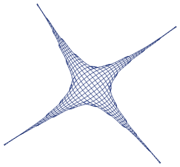
However you still got the problem of long tails.

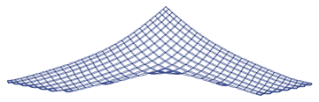
I found it nicer to pre generate a (partial) pattern using just r1 and then fill is seperatly.
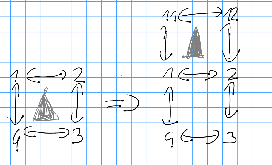
enter image description here

The current rules:

enter image description here

enter image description here

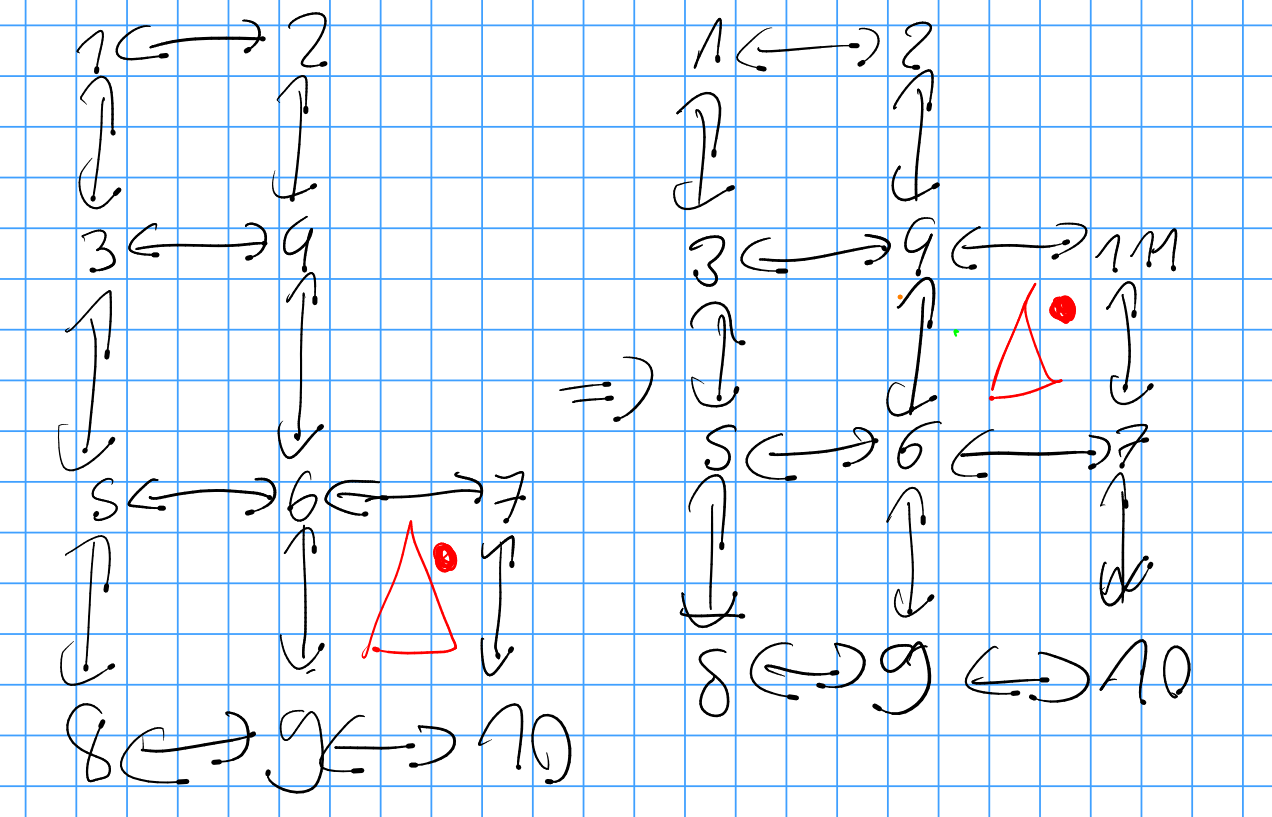
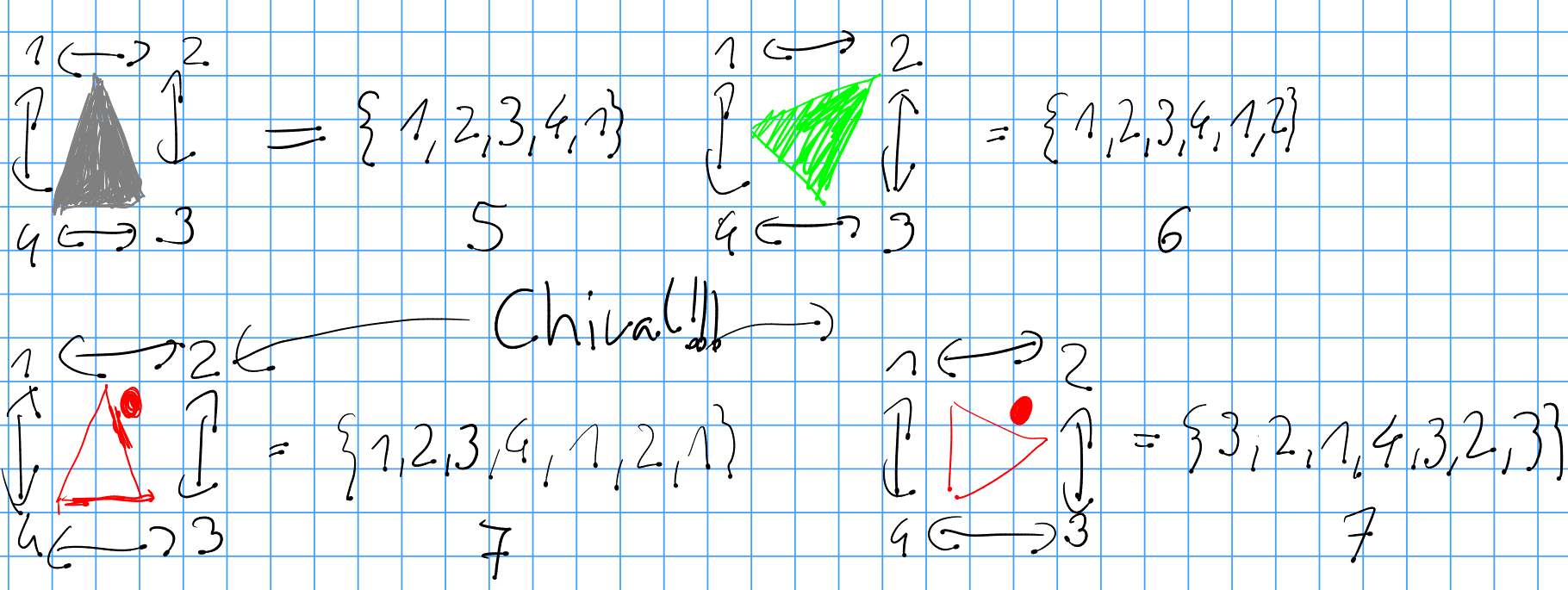
My represenations are not chiral, so i ran into problems with red, which could be solved by understanding that the problem was created by chirality.

enter image description here

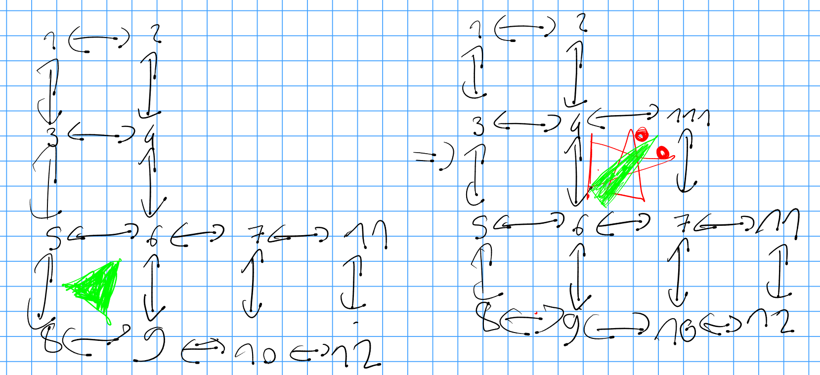
The dot always points away from the coordinate axis.

enter image description here

The code looks like that:

WolframModel[{
    {
     {5,6,9,8,5,6},
     {1,2},{2,1},{2,4},{4,2},{4,3},{3,4},{3,1},{1,3},
     {4,6},{6,4},{6,5},{5,6},{5,3},{3,5},
     {6,9},{9,6},{9,8},{8,9},{8,5},{5,8},
     {6,7},{7,6},{7,10},{10,7},{10,9},{9,10},
     {7,11},{11,7},{11,12},{12,11},{12,10},{10,12}
    } -> {
     {4,111,7,6,4,111,4},
     {7,111,4,6,7,111,7},
     {4,111,7,6,4,111},
     {1,2},{2,1},{2,4},{4,2},{4,3},{3,4},{3,1},{1,3},
     {4,6},{6,4},{6,5},{5,6},{5,3},{3,5},
     {6,9},{9,6},{9,8},{8,9},{8,5},{5,8},
     {6,7},{7,6},{7,10},{10,7},{10,9},{9,10},
     {7,11},{11,7},{11,12},{12,11},{12,10},{10,12},
     {4,111},{111,4},{111,7},{7,111}
    },
    {
     {6,7,10,9,6,7,6},
     {1,2},{2,1},{2,4},{4,2},{4,3},{3,4},{3,1},{1,3},
     {4,6},{6,4},{6,5},{5,6},{5,3},{3,5},
     {6,9},{9,6},{9,8},{8,9},{8,5},{5,8},
     {6,7},{7,6},{7,10},{10,7},{10,9},{9,10}
    } -> {
     {4,111,7,6,4,111,4},
     {1,2},{2,1},{2,4},{4,2},{4,3},{3,4},{3,1},{1,3},
     {4,6},{6,4},{6,5},{5,6},{5,3},{3,5},
     {6,9},{9,6},{9,8},{8,9},{8,5},{5,8},
     {6,7},{7,6},{7,10},{10,7},{10,9},{9,10},
     {4,111},{111,4},{111,7},{7,111}
    },
    {{1,2,3,4,1},{1,2},{2,1},{2,3},{3,2},{3,4},{4,3}}->
        {{11,12,2,1,11},{1,2},{2,1},{2,3},{3,2},{3,4},{4,3},{11,1},{1,11},{11,12},{12,11},{12,2},{2,12}}
},{
    {1,2,3,4,1},{2,3,4,1,2},{3,4,1,2,3},{4,1,2,3,4},
    {1,2,3,4,1,2},{2,3,4,1,2,3},{3,4,1,2,3,4},{4,1,2,3,4,1},
    {1,2},{2,1},{2,3},{3,2},{3,4},{4,3},{4,1},{1,4}
}
, 32, "FinalStatePlot"]

Thank You, Malthe Andersen,

after solving this toy problem, we can strive to attack bigger problems. The solution has more potential for optimization to run faster but now we can finaly say that we can build a 2d grid.

That proposal is not quiet right but i got an idea. I am testing

Look at the attached PDF for another proposal.

It is not as lean as your design, but getting it working should be the first priority. Optimization can happen later. Naturally we still run into the problem that filling out the square areas takes longer than growing a line but that will stay around since we are restricted by some notion of causality.

Attachments:

Can you consider this design, where the colored triangle represent a oriented hyper edge which can be distinguished from each other.

enter image description here

enter image description here

enter image description here

Using the first rule alone i got it to evolve like this for 5 generations before funky stuff happens:

enter image description here

Bu i think i screwed up something else since the next step is wrong.

enter image description here

I have an idea how i can salvage your design if you give me a few more minutes,

As far as I can see, the code does not include the idea of negations, which is why squares are created where they should not.

But thanks for sharing this. There is certainly a mistake in my example, since (in my head) I applied the rule everywhere possible simultaneously each time. I will look some more at this when I have the time.

If negations should be simulated, it would probably require some updating of the code, since the idea is not implemented yet. But they can still be used as analytical tools. And even though my example ended up being wrong, I hope that some of the ideas could still be of use. Especially the idea about subrules.

POSTED BY: Malthe Andersen

I have tried to reproduce your work and have written the rules as such. I hope they are free of careless error

WolframModel[{
    {{1,2},{2,1},{2,3},{3,2},{3,4},{4,3}}->
        {{1,2},{2,1},{2,3},{3,2},{3,4},{4,3},{22,2},{2,22},{22,23},{23,22},{23,3},{3,23}},
    {{1,2},{2,4},{4,2},{2,3},{3,2},{4,6},{6,4},{5,6},{6,5},{6,7},{7,6},{6,8},{8,6},{7,9},{9,7}}->
        {{1,2},{2,4},{4,2},{2,3},{3,2},{4,6},{6,4},{5,6},{6,5},{6,7},{7,6},{6,8},{8,6},{7,9},{9,7},{4,111},{111,4},{111,7},{7,111}},
    {{1,2},{2,4},{4,2},{2,3},{3,2},{4,6},{6,4},{5,6},{6,5},{6,7},{7,6},{6,8},{8,6},{7,9},{9,7},{7,10},{10,7},{11,10}}->
        {{1,2},{2,4},{4,2},{2,3},{3,2},{4,6},{6,4},{5,6},{6,5},{6,7},{7,6},{6,8},{8,6},{7,9},{9,7},{7,10},{10,7},{11,10},{4,111},{111,4},{111,7},{7,111}}
}


,{{1,2},{2,1},{2,3},{3,2},{3,4},{4,3},{4,1},{1,4}}
, 5, "FinalStatePlot"]

Those result in this rule plot:

enter image description here

It is distorted by the graph plotting style but the topology looks correct.

This rule with these initial conditions:

enter image description here

follows this cancerous evolution.

enter image description here

enter image description here

enter image description here

enter image description here

The problem it that r1 can make it grow in any direction and can start to grow from any square. I already devised an approach based on hyper graphs to trim the space of allowed extensions in something close to a plane. Do you want to revise your strategy?

Do you have a recent version of Mathematica available?

I was actually inspired by your post to try to generate a 2D-grid. I tried using triangles and squares, but found that no matter what I always needed several different kinds of rules in order to merge or remove some of the triangles or squares that would be produced excessively. And I somehow needed to limit what points (that is, the valency of the vetices) the rules applied to. This is where my idea about subrules and negations came from. The rest of the new notations is simply making life easier.

POSTED BY: Malthe Andersen

I agree that a lack of negation imposes certain restrictions.

I tried to transcribe your rules from the pictures but the results were very unsatisfactory, as nothing prevents it from growing multiple northward arms from the central piece. I will post results soon as the first renders are out.

You might want to look into my "Failing to make a grid" post to get an idea how HyperGraphs might be used as markers to prevent this ill.

About negation: I don't think it has been applied in the model as of yet, but I see no reason why it wouldn't be allowed. The ultimate goal of all of this is to create a physical theory by using abstract graphs and rules to update these graphs. I see no physical reason why negation cannot be part of such a rule. Of course, it might not be needed in the end, but we cannot know that yet. The graphs you can generate without negations is certainly a subset of the graphs you can generate with it, but showing that those two sets are equal or that a physical theory does not need negations would be a nice discovery in my head. Or maybe one can show that negations lead to contradictions (which I doubt).

I do not have a code for that yet, unfortunately. I was only expanding on the current model, and demonstrated that some of these new notations made it easier to generate graphs of your desire.

About the points: I only drew the most crucial of them, while the "open" arrows simply indicate "something more". I tried to do my best to demonstrate the effect of each subrule.

POSTED BY: Malthe Andersen

Cool. I've been struggling to create a grid.

As far as i am aware it is not possible to create a negation in the WolframModel.

Do you have a code which produces those graphs using the WolframModel framework?

Why isn't the upper left point in r2 and r3 drawn?

Reply to this discussion
Community posts can be styled and formatted using the Markdown syntax.
Reply Preview
Attachments
Remove
or Discard

Group Abstract Group Abstract