
Recognize your favorite snack or beverage in the above pictures? No worry, it is a catoptric- or mirror anamorphosis. These are distorted images that can only be seen undeformed when reflected in a mirror from a prescribed point of view. This contribution will explain how the above and other images are made with the help of Mathematica. To set up an anamorphic experiment, one needs 3 items: a (curved) mirror, a (deformed) anamorphic surface and a defined point of view. For the setup here, the mirror, where we want the undeformed image reflected, is a chrome plated right cone, also used in a previous experiment "Optical Illusions and Self-Anamorphism in a Conical Mirror". The anamorphic surface , where the deformed image will be, is the wall of a plastic open top right cylinder arranged around the conical mirror. The point of view is at infinity on the central axis of both cone and cylinder (the z-axis).
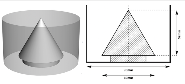
Let us take a look at the geometry of the setup: (due to the radial symmetry we show only one half of a cross section) the triangle TAO is a cross section of the cone and the line DE is a cross section of the cylinder wall.
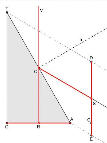
S is a point on the cylinder wall ED. A ray of light emitted by S is reflected by the mirror at Q and meets the eye at V. n is the normal on the cone surface at Q.The eye looks down from V and perceives the point as the point R reflected in the conical mirror. In other words: R is the reflection of S and S is the anamorphic map of R. The cone has a base radius rk of 30mm and a height hk of 52mm which makes an opening angle of 60 degrees. The surrounding cylinder has a radius rc of 47.5mm. With the Cartesian coordinates of a point R in the cone's base, the following function computes the coordinates of S in a development along the wall of the cylinder:
anaCone2Cylinder[{xr_, yr_}, rc_ : 47.5] /; xr^2 + yr^2 <= 1800 :=
 Module[{rk = 30., \[Alpha] = 30 Degree, ri, ti, ra},
  (*polar coordinates of R*){ri, ti} = {Sqrt[xr^2 + yr^2],
    ArcTan[xr, yr]};(*ordinatee of the pointS*)
  ra = -(rc - ri) Cot[2 \[Alpha]] + (rk - ri) Cot[\[Alpha]]; {rc ti,
   ra}]
This shows both domain (left) and range {right) of the function anaCone2Cylinder as a 20 by 20 lines raster. The domain is the base of the cone and the range is the development of the cylinder wall.

We can now test this function on an image defined by a set of points. A first experiment is to use a club suit letter-form available in Mathematica and convert it to a set of points scaled to fit inside the base of the cone:
clubPts =
  5 MeshCoordinates[
    BoundaryDiscretizeGraphics[
     Text[Style["\[ClubSuit]", Bold]], _Text,
     MaxCellMeasure -> 0.1]];
Graphics[{Circle[{0, 0}, 30], AbsoluteThickness[3], Blue,
  Line[clubPts]}, Axes -> True, AxesStyle -> Small]
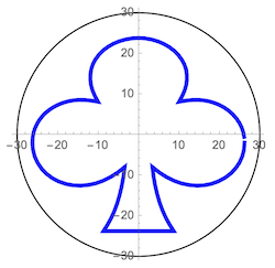
After applying anaCone2Cylinder to the set of points, we get a development of its anamorphic map on the cylinder wall.
anaClbPts = anaCone2Cylinder[#] & /@ clubPts;
Graphics[{AbsoluteThickness[6], Blue,
  Line[Select[Partition[anaClbPts, 2, 1],
    EuclideanDistance @@ # < 10 &]]}, Axes -> True,
 AxesStyle -> Small]

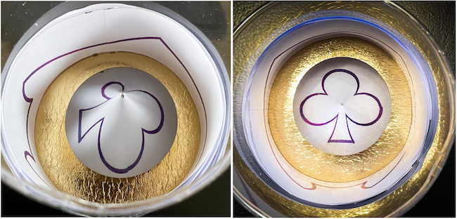
This is the result of printing the above and fitting it inside the cylinder. The anamorphic print on the cylinder wall reflects as the original (virtual ) image in the base of the conical mirror:
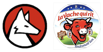
Circular logos are ideal material to use here since they can completely fill the base of the cone without any "overflow". The following two logos are used here and are in full resolution on the attached notebook "usedLogos.nb"
{wolf, cow} = usedLogos;
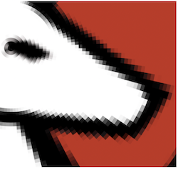
To apply our function anaCone2Cylinder, we need to convert the logo images to a radial set of colored polygons. The function ImageRadialDivide that I submitted to the Wolfram Function Repository is ideal for this. This is a partial magnification of the wolf logo that shows the radially aligned polygons:
Graphics[ResourceFunction["ImageRadialDivide"][
  ImageReflect[wolf, Left]]]
We then use the same procedure as with the club suit image and get the following cylinder development:
wolfPolys =
  ResourceFunction["ImageRadialDivide"][ImageReflect[wolf, Left]];
anaWolfPolys =
  wolfPolys /. {x_?NumericQ, y_} -> anaCone2Cylinder[30 {x, y}];
Graphics[anaWolfPolys]

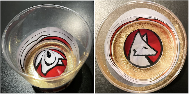
The result of fitting the printout of the development inside the cylinder and reflecting it in the central mirror:
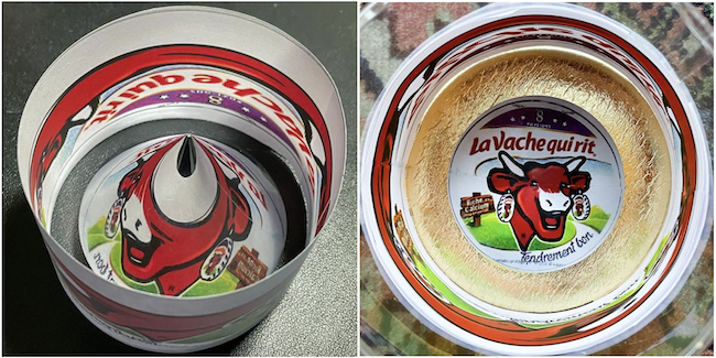
The same procedure can be repeated for the "laughing cow" logo to get the following:
cowLogo = ImageReflect[ImageResize[cow, 400], Left];
cowPolys = ResourceFunction["ImageRadialDivide"][cowLogo];
anaCowPolys =
  cowPolys /. {x_?NumericQ, y_} -> anaCone2Cylinder[30 {x, y}];
Graphics[anaCowPolys]

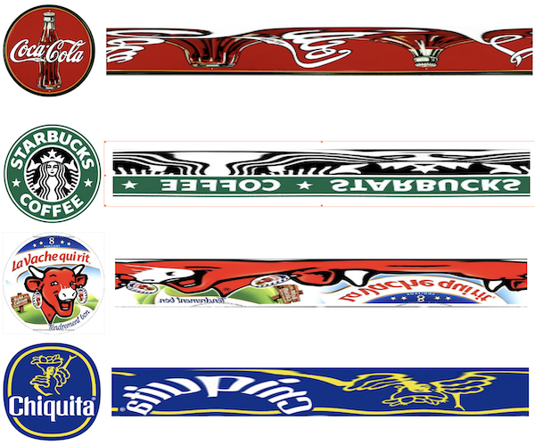
Finally, here are some more famous logos with their anamorphic deformation (right) and the corresponding reflection (left) in a conical mirror .
 Attachments: