Message Boards Message Boards

0
|
3964 Views
|
7 Replies
|
2 Total Likes
View groups...
Share
Share this post:

Pruning removes an extra point

Dear all,

I am using the function for pruning and want it to remove one point at a time from each end of a line. But just when it is almost done, it unexpectedly removes three points. Can anyone explain this behavior? Is there a workaround?

img0 = Image[{{0, 0, 0, 0}, {0, 0, 1, 0}, {0, 0, 1, 0}, {0, 1, 0, 
    0}, {0, 1, 0, 0}, {0, 0, 1, 0}, {0, 0, 1, 0}, {0, 0, 1, 0}, {0, 0,
     1, 0}, {0, 0, 0, 0}}]
FixedPointList[Pruning[#, {1}] &, img0]

In the 1st and 2nd round, it removes 2 points, but 3 points in the 3rd round.

In the end, I want to convert the line to a vector object, so I thought with pruning I can get two points at a time, then reverse one of the traces and connect it to the other one. But this behavior makes it more complex.

Thanks for your ideas!

Max

7 Replies

Good evening Henrik, your code looks quite good and is very fast. I think the two prominent directions are artefacts though. If I rotate the image by a random value, the peaks remain where they are. Probably the gradient function treats certain angles with a preference. This is also true for my algorithm but not to that extent. If I play with the cutoff for the refinement of the subdivision (the value 0.5 in the function "splt"), the algorithm also allows bigger deviations from the exact line, therefore also more variations in the angle of the line. I assume it is indeed a difficult issue to get a true representation of the real angular distribution, i.e. the ground truth of the underlying data, which is what we try to obtain.

We use a SEM to look at structures on a cell surface and want to test the hypothesis that they are aligned with the orientation of the tissue. First, I obtained the outline of the structures with U-Net, then I determined their center line with SkeletonTransform and Thinning. Actually I did not really phrase it correctly previously; it is not so much about finding a preferential direction but more about determining if there is an alignment with the orientation of the tissue. For this image, the anterior/posterior axis of the sample is at 18 deg, counted from the horizontal direction counterclockwise. We would assume a preference of the structures to align either parallel or perpendicular to the axis.

Good night,

Max

enter image description here

Hello Henrik,

the ImageGraphics function is generating the outline, but I want to trace the line itself from one end to the other. And although FindShortestTour is elegant, it is quite slow. I have tens of images with around 1000-2000 lines each. So ideally it should vectorize one line within tens of milliseconds. Less than a second is still acceptable.

In the end, the goal is to have a distribution of angles present in all the lines and see if there is a preference for a certain angle; so it is essential to smoothen the lines a bit to not only get 0°; 45° and 90°.

Max

enter image description here

Hi Max,

In the end, the goal is to have a distribution of angles present in all the lines and see if there is a preference for a certain angle;

OK - new attempt! Maybe you can use GradientOrientationFilter; the result is an image consisting of the directional gradient data, ranging between -Pi/2 and +Pi/2: these data can be examined statistically (let img be the image above):

cnImg = ColorNegate@img;
gof = GradientOrientationFilter[cnImg, 3];
Histogram[gof // ImageData // Flatten, PlotRange -> {All, {0, 30000}}]

enter image description here

The big bar in the middle is just the background; but you see that two directions seem to be prominent.

Does that now got into the right direction? Regards -- Henrik

POSTED BY: Henrik Schachner

Hi Max, somehow your problem keeps me occupied! Here come two more ideas which - I think - can deal with branches. As test image I am using this image:

enter image description here

The first option is to use FindShortestTour and remove any resulting long jumps (the code should be self explaining):

testImg = << "testImg.txt";
pts = ImageValuePositions[testImg, 1];
ptso = pts[[Last@FindShortestTour[pts]]];
bigJumps = Select[MapIndexed[{First[#2], #1} &, 
    BlockMap[EuclideanDistance @@ # &, ptso, 2, 1]], Last[#] > 5 &];
splitIndx = First /@ bigJumps;
Set[ptso[[#]], "marker"] & /@ splitIndx;
ptso1 = SequenceSplit[ptso, {"marker"}];
Graphics[{Red, Thick, Line /@ ptso1}]

The other option is to "hijack" the function ImageGraphics, which results in a tightly enclosing line:

ig = ImageGraphics[testImg, Method -> "Exact"];
igPts = Cases[Normal[ig], FilledCurve[__], Infinity][[2, 1, 1, 1, 1]];
Manipulate[Graphics[{Line[igPts[[;; n]]]}, Frame -> True, 
  PlotRange -> CoordinateBounds[igPts]], {n, 1, Length[igPts], 1}]

Does that help? Regards -- Henrik

Attachments:
POSTED BY: Henrik Schachner

Hello Henrik,

I want a reduction of my line to segments, like a vectorization. So eventually I came up with this code. Maybe someone has a more elegant way of solving this, but it works, as long as it is a line without branching points.

When you skeletonize the object and remove branching points beforehand, the code works fine. Otherwise it generates a mess or errors, unfortunately.

(* example array *)
arr = {{0, 0, 0, 0, 0, 0, 0, 0, 0, 0, 0, 0, 0, 0, 0, 0, 0}, {0, 0, 0, 
0, 0, 0, 0, 0, 0, 0, 0, 0, 0, 1, 0, 0, 0}, {0, 0, 0, 0, 0, 0, 0, 
0, 0, 0, 0, 0, 1, 0, 1, 0, 0}, {0, 0, 0, 0, 0, 0, 0, 0, 0, 0, 0, 
1, 0, 0, 1, 0, 0}, {0, 1, 1, 0, 0, 0, 0, 0, 0, 0, 1, 0, 0, 0, 1, 
0, 0}, {0, 0, 0, 1, 1, 0, 0, 0, 0, 1, 0, 0, 0, 0, 0, 1, 0}, {0, 0,
0, 0, 0, 1, 1, 1, 1, 0, 0, 0, 0, 0, 0, 1, 0}, {0, 0, 0, 0, 0, 0, 
0, 0, 0, 0, 0, 0, 0, 0, 0, 0, 0}};

(* removes one point from each end and sows point *)
prune[arr_] := 
 ReplacePart[
  arr, # -> 0 & /@ 
   Sow[Position[ListConvolve[BoxMatrix[1], arr, {2, -2}, {0}]*arr, 2]]]
(* connects point to nearest end of existing chain *)
chain[c0_, m_] := 
 If[ChessboardDistance[c0[[1]], m] == 1, Prepend[c0, m], Append[c0, m]]
(* repeatedly cuts ends and connects them all together *)
lin[arr_] :=
 (
  ends = Flatten[Reap[FixedPoint[prune, arr]][[2]], 2];
  Fold[chain, {ends[[-1]]}, Drop[Reverse[ends], 1]]
  )

(* calculate distance of point from line segment, found in \
Mathematica commuity example *)
d[a_, b_, p_] := 
  If[a == b, 
   Norm[p - a], {pz, az, bz} = Map[First[#] + Last[#] I &, {p, a, b}];
    z = (pz - az)/(bz - az); 
   If[Not[0 <= Re[z] <= 1], Min[Norm[p - a], Norm[p - b]], 
    Norm[Im[z] (b - a)]]];
(* split line into two at biggest distance point, if this distance is \
bigger than 0.5 *)
splt[pts_] :=
 (
  dlst = N[d[pts[[1]], pts[[-1]], #] & /@ pts];
  p0 = Ordering[dlst, -1][[1]];
  If[dlst[[p0]] > 0.5, {Take[pts, p0], Drop[pts, p0 - 1]}, {pts}]
  )
(* flatten array with point lists *)
spltl[ptsl_] := Flatten[splt /@ ptsl, 1]
(* split list until no further change, remove double intermediates *)
lred[pts_] := Append[#[[1]] & /@ FixedPoint[spltl, {pts}], pts[[-1]]]


(* now initial split is done, then refinement of points by wiggling \
left and right *)
(* total distances in one line segment *)
sd[pts_, n1_, n2_] := 
 Plus @@ (d[pts[[n1]], pts[[n2]], #]^2 & /@ 
    pts[[Range[n1 + 1, n2 - 1]]])
(* total distances in whole line *)
ssd[pts_, nlst_] := 
 Plus @@ (sd[pts, #[[1]], #[[2]]] & /@ Partition[nlst, 2, 1])
(* wiggle each intermediate point by one left and right, find point \
list that has the minimal sum *)
ptssm[pts_, nlst_] :=
 (
  l0 = {nlst};
  (AppendTo[l0, ReplacePart[nlst, # -> nlst[[#]] - 1]]; 
     AppendTo[l0, ReplacePart[nlst, # -> nlst[[#]] + 1]]) & /@ 
   Range[2, Length[nlst] - 1];
  SortBy[l0, ssd[pts, #] &][[1]]
  )
(* repeat until no further change *)
lred1[pts_] := (pts0 = N[pts]; 
  pts0[[FixedPoint[ptssm[pts0, #] &, 
    Flatten[Position[pts0, #] & /@ lred[pts0]]]]])

Graphics[{Raster[Transpose[arr]], Red, Thick, 
  Line[# - {0.5, 0.5} & /@ lred1[lin[arr]]]}, ImageSize -> 100]
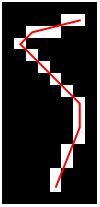
image

I hope that someone might find this useful.

Best, Max

Hello Max,

ahh, I see what you meant! Now - just as a footnote - here is another attempt (using your example array arr from above):

img = Image[arr, ImageSize -> 400];
pts = ImageValuePositions[img, 1];
endPts = ImageCorners[img, MaxFeatures -> 2];
{start, end} = Flatten[Position[pts, #] & /@ endPts];
order = Last@FindShortestTour[pts, start, end];
GraphicsColumn[{Show[img, Graphics[{Red, Thick, Line[pts[[order]]]}]],
   Show[img, Graphics[{Red, Thick, BSplineCurve[pts[[order]]]}]]}]

enter image description here

Maybe this is in a way helpful, regards -- Henrik

POSTED BY: Henrik Schachner

Hi Max,

In the end, I want to convert the line to a vector object, ...

I am not sure about your intention, but maybe this helps:

I start with an object like this (coming from the new and useful function Canvas):

enter image description here

Then I basically use ComponentMeasurements to calculate the data needed for a vector representation:

img = Binarize[Image @@ obj];
cm = ComponentMeasurements[ColorNegate[img], {"Centroid", "Orientation"}];
arrows = With[{v = {Cos[#2], Sin[#2]}, l = 25}, {#1 + l v, #1 - l v}] & @@@ cm[[All, 2]];
Show[img, Graphics[{Red, Arrow /@ arrows}]]

enter image description here

Liebe Gruesse ins schoene Freiburg! -- Henrik

POSTED BY: Henrik Schachner
Reply to this discussion
Community posts can be styled and formatted using the Markdown syntax.
Reply Preview
Attachments
Remove
or Discard

Group Abstract Group Abstract