Group Abstract Group Abstract

Message Boards Message Boards

0
|
9.9K Views
|
6 Replies
|
3 Total Likes
View groups...
Share
Share this post:

Problems with flywheel simulation and attachment

Posted 4 years ago

I have a mathematical Block Model of a current controlled bldc motor, this model includes the motors parameters itself, including that of a flywheel, This model works exactly the way I expect it to, producing the same plots and dynamics as my mathematica fitted model.

enter image description here

I would now like to separate the 'flywheel' part of this, and connect a fixed BodyShape with a Rotor1D from another multibody model I have. The intention is to study the gyroscopic effects and later develop an angular momentum controller.

My assumptions where I could simply attach my mathematical model to a Torque and then the BodyShape with the parameters of the flywheel itself. I have made a working test example to attempt this, my expectations being that the motor dynamics would remain unchanged. However this appears to not be the case.

enter image description here

I have attached the test example, plus the flywheel motor. The variable J being the inertia of the system has currently the value (0.0000135), while in the first imaged example (where the flywheel is included in the mathematical model, J would be 0.00013612480196014234 )

The test example, is what i how I planned to attach models together, namely motor -> flywheel -> fixed translation of multibody like so:

enter image description here

In the test example, world would be the step-in for the fixed translation. How do I attach my mathematical model to the multibody one?

If there is a way to simply attach my already verified mathematical model to a fixed translation in a a multi body model and then be able to study the effects, I'd also love to know how, either solution would be great however.

Thanks!

Attachments:
POSTED BY: Mor Bo
6 Replies
POSTED BY: Ankit Naik
Posted 4 years ago
POSTED BY: Mor Bo
Posted 4 years ago

Hello Neil!

Wow thank you as usual for your exceptional explanation and the examples.

To get to your questions directly:

Is this what you are looking for? Basically yes. My model as I said, will be a Cube satellite, with motor drive inertias, and as such (beyond the sphereical joint) what you've modelled is pretty much what each sub system (motor, controller and rotor) will end up being.

Why do you want to use a "mathematical motor"?

This probably requires some more explanation. To be frank, it's mostly because I don't know how to use those finished models.

In the real system, I am using a EC 45 Flat motor (251601) plus their current controller (see attached PDF) from maxon motor. With the controller, I can drive the motor with a current source. Their data sheet has quite a bit of information about the motor itself, however when attempting to use the built-in model SM_PermanentMagnet and the subsequent example SMPM_CurrentSouce which at the time I assumed would be a perfect starting point.

current source

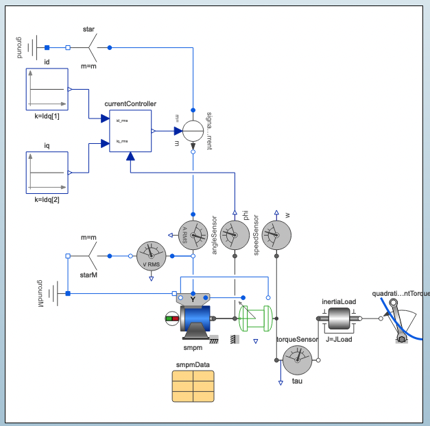
I am completely overwhelmed with how it's set up and how to give correct data compared to my real life motor and controller, that I can actually do anything with. Lmd and Lmq, LD and LQ values and most other variables which work in the example, are vastly different to the values from the data sheet and I have no current way to measure or figure them out myself, maxon as a company also refuses to give anything more than the public facing catalogue data.

However, my mathematical ODE model represents the motors with their controller quite accurately, which I've verified and used for this project (https://www.youtube.com/watch?v=Lzw3ZGTuMUU) (which is one of the walls of the cube sat), and since I already had a model that does what I wanted, I decided it was the fastest route, rather than trying to hack the examples together.

I would absolutely appreciate if you could show me an example of how to improve my model with the rotational flanges, or to make it more physical in any other way. When attempting myself, I realise now that mixing and matching different blocks isn't as easy as I'd hope. The rotational flange only accepts rotational connections it seems...

As as side question, Do you have any suggestions for material, tutorials or likewise for the 'modelica method' you mention? It's difficult to find literature that is suited for beginners for this modeling concept, and my only experience as you accurately deduced, is simulink, which clearly isn't appropriate.

Thank you again for the detailed answer, I very much appreciate the help.

Attachments:
POSTED BY: Mor Bo
Attachments:
POSTED BY: Neil Singer

I don't think I completely understand your issue. The flywheel motor model seems to work fine.

Although you have a problem in the way you are using the rotor and Body. Currently, the body is completely stationary throughout the simulation (is it supposed to be??). You are attaching it to the reference frame for the rotor1D, but you give it no motion or torque so it does nothing. For this reason it does not contribute to the simulation in any way (you can prove this to yourself by disabling it and connecting the rotor to ground -- the simulation results are identical.

Look at the GyroscopicEffects example in the Multibody library (Modelica.Mechanics.MultiBody.Examples.Rotational3DEffects). This should help you, but I am really not clear on how you want to use your flywheel model and connect it.

Regards,

Neil

POSTED BY: Neil Singer
Posted 4 years ago

Hello Neil!

The flywheel motor model does indeed work fine. I guess perhaps my naming convention is confusing....sorry about that. I want to do one of two things, either:

1) Attach my flywheel_motor_model.mo, where variable J is equal to 0.00013612480196014234 to a fixed translation and Revolute in a different multibody model and then study the gyroscopic effects.

2) or I would like to attach a mathematical motor model where J is equal to 0.000013.... we can call it current_control_motor.mo, and use it to apply a torque to the objects Bodyshape + Rotor1D, which are suppose to represent just the flywheel, which are all connected on said different multibody model, so namely, an assembly of flywheel and motor connected to the different mulitbody model.

My expectations are that 1 and 2 should produce the exact same plots, which in my images they don't as you correctly say, it's likely the objects are all connected wrong and I don't get it.

In the end I want to simulate a cube satellite, with flywheels connected to motors built inside, but I'm having problems, as you say with the Rotor1D, Bodyshape and how to correctly apply my mathematical motor model's torque to these objects.

The flywheel in reality is 103mm in diameter, 6mm thick, 120g with an inertia tensor approx:

I_11 == 0.000122/2 I_22 == 0.000122/2 I_33 == 0.000122

my Expectations are

current_control_motor.mo gets a step signal, and with it connected to the Rotor1D, and Bodyshape they all begin to accelerate in unison as one assembly to the same top angular velocity, 400 1/s, in about 3 seconds.

Currently this does not happen. As you saw, the Revolute, bodyshape and Rotor1D, and current_control_motor.mo motor all have different angular velocities.

I have looked for hours at Gyroscopic3dEffects, and I don't get anywhere closer, unfortunately.

POSTED BY: Mor Bo
Reply to this discussion
Community posts can be styled and formatted using the Markdown syntax.
Reply Preview
Attachments
Remove
or Discard