Message Boards Message Boards

7
|
20050 Views
|
7 Replies
|
35 Total Likes
View groups...
Share
Share this post:

Find polygons corresponding to image borders

Posted 11 years ago
Hi!

I have this image ( map ), which I want to split in to polygons given by the borders: There should be around 300 areas (each light grey area is a distinct area, surrounded by a black, dark grey, or white border). I would need the coordinates of the polygons representing the areas. Thanks for any help with this!

Pri.

POSTED BY: Priyan Fernando
7 Replies
You can actually do this much more simply.

You can get the outside edges of each region by running this:
Colorize@MorphologicalComponents[
MorphologicalPerimeter[Binarize[map, {0.225, 0.275}]],
CornerNeighbors -> False]
If you want to get rid of regions that may have been caused by something like anti-aliasing you can simple add a DeleteSmallComponents[]:
Colorize@MorphologicalComponents[
MorphologicalPerimeter[DeleteSmallComponents[Binarize[map, {0.225, 0.275}]]],
CornerNeighbors -> False]

Once you have that you can get the positions of each edge pixel of a given region.  Then you have the problem of arranging the positions.  It turns out you can actually just use a function called FindShortestTour[].

Putting that all together, and adding some interface elements, you get this:
 comp = MorphologicalComponents[
    MorphologicalPerimeter[Binarize[map, {0.225, 0.275}]],
    CornerNeighbors -> False];
 regions = Rest[Union[Flatten[comp]]];
 n = 0;
 Monitor[
  ParallelMap[
   Function[region, n++;
    Function[position,
     Polygon[RotationTransform[-Pi/2, {0, 0}][
       position[[FindShortestTour[position][[2]]]]]]][
    Position[comp, region]]], regions],
Row[{ProgressIndicator[n, {1, Length[regions]}], Spacer[20],
   ToString[n] <> "/" <> ToString[Length[regions]]}]]


--Chris
Very nice example of using ProgressIndicator within Monitor, Chris!

Bob
POSTED BY: Robert Nachbar
Thank you for your version, Chris. Of course my code is very sloppy. The short version is
components =
  MorphologicalComponents[
   MorphologicalPerimeter[Binarize[image, {0.225, 0.275}],
    CornerNeighbors -> True], 0, CornerNeighbors -> False];

regionNames = Rest[Union[Flatten[components]]];
positions = Table[Position[components, name], {name, regionNames}];
 boxSides[pt_] :=
   Partition[{pt + {-(1/2), -(1/2)}, pt + {1/2, -(1/2)}, pt + {1/2, 1/2}, pt + {-(1/2), 1/2}}, 2, 1, 1];
 signarure[path_] := Positive@Total[Det /@ path]
 
 contour[pts_] :=
  Module[{edges = Join @@ (boxSides /@ pts), graph, tours},
   graph = Graph[DirectedEdge@@@Complement[edges, Intersection[edges, Reverse /@ edges]]];
   tours = List@@@First@FindPostmanTour@Subgraph[graph, #]&/@ConnectedComponents@graph;
   First /@ First@Select[tours, signarure]]

polys = ParallelMap[
   Polygon[RotationTransform[-Pi/2, {0, 0}][contour[#]]] &, positions];
Not it is much faster.

The only excuse I have is that the function "contour" can be used for accurate vectorization while FindShortestTour is not a robust function. For example, let's consider a comma-like image.
image = ColorNegate@
   Binarize@Rasterize[Graphics[{Disk[{0, 0}], Circle[{-2, 0}, 3 , {-Pi/3, 0}]}], ImageSize -> 25];

comp = ImageData@MorphologicalPerimeter[image];
pos = Position[comp, 1];
Now you can clearly see the difference:
Graphics[{
  {ColorData[2, "ColorList"][[1]], Thick,
   Polygon[RotationTransform[-Pi/2, {0, 0}][contour[pos]]]},
  {Opacity[0.7], ColorData[2, "ColorList"][[7]], Thick,
   Polygon[RotationTransform[-Pi/2, {0, 0}][pos[[FindShortestTour[pos][[2]]]]]]}}]
POSTED BY: Grisha Kirilin
Posted 11 years ago
Thanks for this Grisha! Amazing piece of analysis and I wouldn't have been able to figure this on my own!
It also make me think how great our eyes and brains are, in being able to discern the boundaries quite easily. Thanks again!
POSTED BY: Priyan Fernando
I wouldn't say that there is a problem with the recognition of regions. Only two line of code yield a desired result:
image = ColorNegate@ColorConvert[Import["http://upload.wikimedia.org/wikipedia/commons/c/c7/Sri_Lanka_divisions.png"], "Grayscale"];
MorphologicalComponents[Binarize[image, {0.225, 0.275}], 0, CornerNeighbors -> False] // Colorize


The problem is to explain to machine the form you want the information to be represented.
POSTED BY: Grisha Kirilin
Grisha,

Your last remark about representing the information is so very true. I don't think enough attention is given to mastering that art!

Bob
POSTED BY: Robert Nachbar
Hi Priyan,

there are two steps in the problem: extraction of the regions from the picture and extraction of the perimeters from every region. The first step can be performed via precise binarization.
image = ColorNegate@ColorConvert[Import["http://upload.wikimedia.org/wikipedia/commons/c/c7/Sri_Lanka_divisions.png"], "Grayscale"];

size = ImageDimensions[image];
imageXY[{y_, x_}] := {x, size[[2]] + 1 - y};
We need two parameters:
threshold = {0.225, 0.275};
minRegionArea = 17;
The first one is the thresholds for binarization and the last one is the minimal area of a region. The first parameters can be found form the image histogram:
ImageHistogram[image, FrameTicks -> {Range[0, 1, 0.1], None}, ImageSize -> 900]
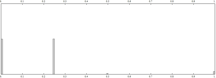
One can see that the second most popular color is inside the thresholds chosen. The binarization and regions can be found as follows:
image2 = Binarize[image, threshold];

components = MorphologicalComponents[image2, 0, CornerNeighbors -> False];
count = ComponentMeasurements[components, "Count"];
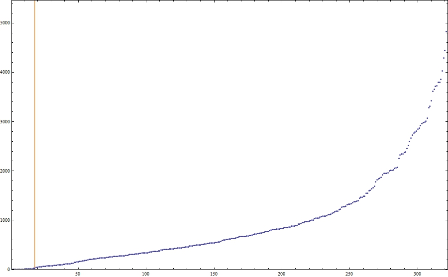
One can see that there are a lot of small artefacts, thus we need to remove them:
areas = Union[Last /@ count];
ListPlot[areas, Frame -> True, ImageSize -> 900, PlotRange -> All, PlotRangePadding -> None,
Prolog -> {Orange, Line[{Scaled[{minRegionArea/Length@areas, 0}], Scaled[{minRegionArea/Length@areas, 1}]}]}]
The value of minRegionArea is demonstrated by the orange line in the figure below:
regionNames = First /@ Select[count, Last[#] > minRegionArea &];
The most hard part is to extract boundaries. The first step is to find the position of the morphological perimeters:
positions = Table[Position[components ImageData[MorphologicalPerimeter[image2, CornerNeighbors -> True], "Bit"], name], {name, regionNames}];
This function works really slow so be patient. Then we need two auxiliary functions:
boxSides[pt_] := Partition[{pt + {-(1/2), -(1/2)}, pt + {1/2, -(1/2)}, pt + {1/2, 1/2}, pt + {-(1/2), 1/2}}, 2, 1, 1];

signarure[pts_] := Positive@Total[Det /@ Partition[pts, 2, 1, 1]];
The first one yields the sides of the box around each pixel in the counterclockwise order. The second one gives True if the sequence of points corresponds to a contour ordered counterclockwise. The core is the following function:
contour[pts_] := Module[{vectors = Join @@ (boxSides /@ pts),
   vertices, edges,
   graph, tours},
  vertices = Union[First /@ vectors];
  edges = vectors /. Thread[vertices -> Range@Length@vertices];
  graph = Graph[DirectedEdge @@@ Complement[edges, Intersection[edges, Reverse /@ edges]]];
  tours = (First /@ First@FindPostmanTour@Subgraph[graph, #]) & /@ ConnectedComponents@graph;
  vertices[[First@Select[tours, signarure[vertices[[#]]] &]]]]
The idea is to merge all small contours around each pixel so that only boundaries remain, then the function "signarure" helps us to find the single outer boundary, e.g.,
n = 1;
Graphics[{ColorData[2, "ColorList"][[5]], Polygon[First /@ boxSides[#]] & /@ positions[[n]],
{ColorData[2, "ColorList"][[1]], Thick, Line[Append[#, First@#] &[contour[positions[[n]]]]]}}]
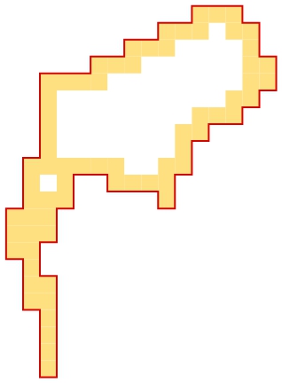
The red line is the boundary we need.
perimeters = ParallelMap[contour, positions]; // AbsoluteTiming
(* {10.821194, Null} *)

boundaries = Map[imageXY, perimeters, {2}];
Unfortunately, this function works terribly slow thus I have to use ParallelMap. The list "boundaries" contains boundaries required.

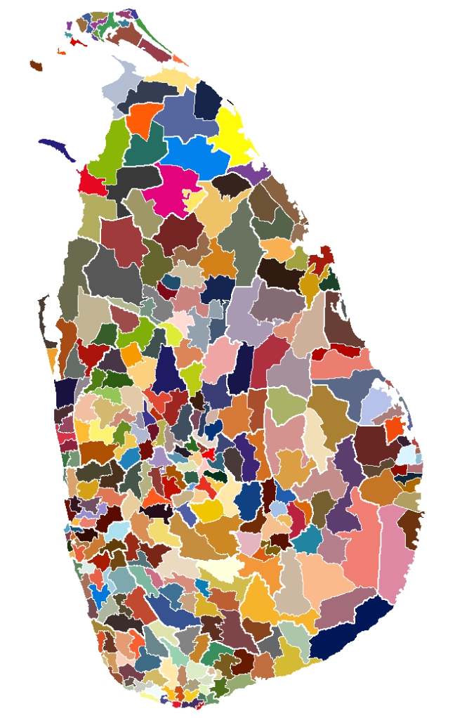
All regions can be demonstrated as follows:
colors = Join @@ Table[ColorData[n, "ColorList"], {n, 1, 60}];
Graphics[Table[{colors[[n]], Polygon[boundaries[[n]]]}, {n, Length[boundaries]}], ImageSize -> size]
The Mathematica file is in the appachment.
Attachments:
POSTED BY: Grisha Kirilin
Reply to this discussion
Community posts can be styled and formatted using the Markdown syntax.
Reply Preview
Attachments
Remove
or Discard

Group Abstract Group Abstract