Hi Priyan,
there are two steps in the problem: extraction of the regions from the picture and extraction of the perimeters from every region. The first step can be performed via precise binarization.
image = ColorNegate@ColorConvert[Import["http://upload.wikimedia.org/wikipedia/commons/c/c7/Sri_Lanka_divisions.png"], "Grayscale"];
size = ImageDimensions[image];
imageXY[{y_, x_}] := {x, size[[2]] + 1 - y};
We need two parameters:
threshold = {0.225, 0.275};
minRegionArea = 17;
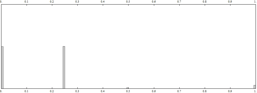
The first one is the thresholds for binarization and the last one is the minimal area of a region. The first parameters can be found form the image histogram:
ImageHistogram[image, FrameTicks -> {Range[0, 1, 0.1], None}, ImageSize -> 900]

One can see that the second most popular color is inside the thresholds chosen. The binarization and regions can be found as follows:
image2 = Binarize[image, threshold];
components = MorphologicalComponents[image2, 0, CornerNeighbors -> False];
count = ComponentMeasurements[components, "Count"];
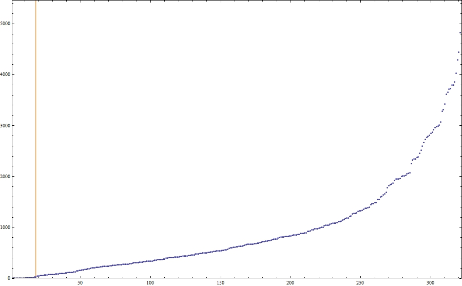
One can see that there are a lot of small artefacts, thus we need to remove them:
areas = Union[Last /@ count];
ListPlot[areas, Frame -> True, ImageSize -> 900, PlotRange -> All, PlotRangePadding -> None,
Prolog -> {Orange, Line[{Scaled[{minRegionArea/Length@areas, 0}], Scaled[{minRegionArea/Length@areas, 1}]}]}]
The value of minRegionArea is demonstrated by the orange line in the figure below:

regionNames = First /@ Select[count, Last[#] > minRegionArea &];
The most hard part is to extract boundaries. The first step is to find the position of the morphological perimeters:
positions = Table[Position[components ImageData[MorphologicalPerimeter[image2, CornerNeighbors -> True], "Bit"], name], {name, regionNames}];
This function works really slow so be patient. Then we need two auxiliary functions:
boxSides[pt_] := Partition[{pt + {-(1/2), -(1/2)}, pt + {1/2, -(1/2)}, pt + {1/2, 1/2}, pt + {-(1/2), 1/2}}, 2, 1, 1];
signarure[pts_] := Positive@Total[Det /@ Partition[pts, 2, 1, 1]];
The first one yields the sides of the box around each pixel in the counterclockwise order. The second one gives True if the sequence of points corresponds to a contour ordered counterclockwise. The core is the following function:
contour[pts_] := Module[{vectors = Join @@ (boxSides /@ pts),
vertices, edges,
graph, tours},
vertices = Union[First /@ vectors];
edges = vectors /. Thread[vertices -> Range@Length@vertices];
graph = Graph[DirectedEdge @@@ Complement[edges, Intersection[edges, Reverse /@ edges]]];
tours = (First /@ First@FindPostmanTour@Subgraph[graph, #]) & /@ ConnectedComponents@graph;
vertices[[First@Select[tours, signarure[vertices[[#]]] &]]]]
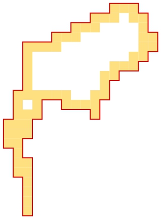
The idea is to merge all small contours around each pixel so that only boundaries remain, then the function "signarure" helps us to find the single outer boundary, e.g.,
n = 1;
Graphics[{ColorData[2, "ColorList"][[5]], Polygon[First /@ boxSides[#]] & /@ positions[[n]],
{ColorData[2, "ColorList"][[1]], Thick, Line[Append[#, First@#] &[contour[positions[[n]]]]]}}]

The red line is the boundary we need.
perimeters = ParallelMap[contour, positions]; // AbsoluteTiming
(* {10.821194, Null} *)
boundaries = Map[imageXY, perimeters, {2}];
Unfortunately, this function works terribly slow thus I have to use ParallelMap. The list "boundaries" contains boundaries required.
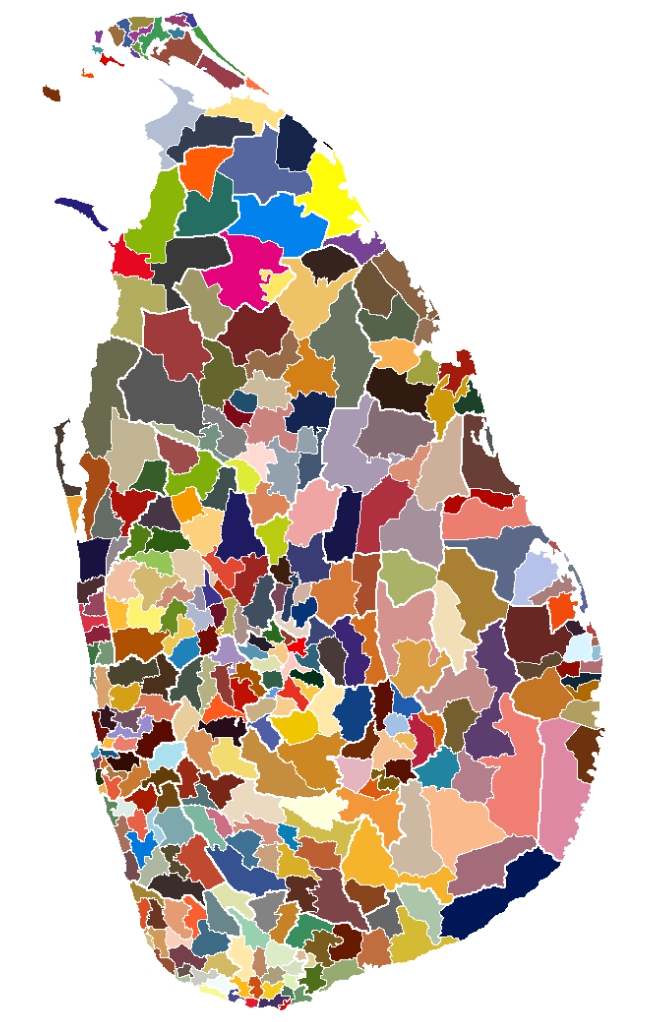
All regions can be demonstrated as follows:
colors = Join @@ Table[ColorData[n, "ColorList"], {n, 1, 60}];
Graphics[Table[{colors[[n]], Polygon[boundaries[[n]]]}, {n, Length[boundaries]}], ImageSize -> size]

The
Mathematica file is in the appachment.
 Attachments: