I went spelunking for some useful utility, but I could not immediately find one so I put something together quickly. It's bound not to be perfect.
The main idea is to take the FeatureExtractorFunction processor information and graph the feature evolution. Let's start with your example:
fe = FeatureExtraction[{{1.4, "A"}, {1.5, "A"}, {2.3, "B"}, {5.4, "B"}}]
and extract the name and input/output part of each processor
processor$edges =
 Rule @@@ Keys@Values@fe[[1, "Processor", 2, "Processors", All, 2, {"Input", "Output"}]]
processor$names = fe[[1, "Processor", 2, "Processors", All, 1]]

(* {{"f1", "f2"} -> {"f1", "f2"}, {"f2"} -> {"f2"}, {"f1",
   "f2"} -> {"(f1f2)"}, {"(f1f2)"} -> {"(f1f2)"}, {"(f1f2)"} -> {"(f1f2)"}} *)

(* {"Threads", "EmbedNominalVector", "MergeVectors", "DimensionReduceNumericalVector", "Standardize"} *)
Now with some replacement we can show how the transformed features are related
Flatten@Replace[
   Transpose[{processor$edges, processor$names}],
   {a_ -> b_, name_} :> {Thread[a \[DirectedEdge] name], Thread[name \[DirectedEdge] b]},
   {1}
   ];
Graph[%, VertexLabels -> Automatic]
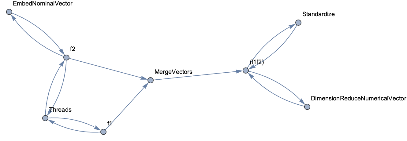
This tells us something already but it is not easy to follow the pipeline evolution. In order to do that we need to process the feature names a bit to modify them whenever the feature is processed (the internal representation only modify the name when splitting or merging features)
This code adds a subscript to the feature name that is incremented when the same name appears on both sides of a processor
resetIndices := (Clear[index]; index[x_] := 1)
rename[x_List] := rename /@ x
rename[old_List -> x_List] := (rename[#, {}] & /@ old) -> (rename[#, old] & /@ x)
rename[x_, old_List] := Subscript[x, If[MemberQ[old, x], index[x] += 1, index[x]]]
I am also going to throw in a couple of functions to style the graph vertices and keep those long processor names from messing up the graph layout
labelFeature[x_] := Framed[Style[x, Black], Background -> LightBlue]
labelProcessor[x_] :=
 Framed[Pane[Style[StringReplace[a_?LowerCaseQ ~~ b_?UpperCaseQ :> a <> "\[InvisibleSpace]" <> b]@x,
     Black], {{60}, Automatic}], Background -> White, RoundingRadius -> 5]
This is the updated replacement code
resetIndices
edges = Flatten@Replace[
    Transpose[{rename@processor$edges, processor$names}],
    {
     {a_ -> b_, name_} /; Length[a] == Length[b] :> MapThread[
       {labelFeature[#1] \[DirectedEdge] Annotation[labelProcessor@name, "type" -> {##}],
         Annotation[labelProcessor@name, "type" -> {##}] \[DirectedEdge] labelFeature[#2]} &,
       {a, b}],
     {a_ -> b_,
       name_} :> {Thread[
        labelFeature /@ a \[DirectedEdge] Annotation[labelProcessor@name, "type" -> {a, b}]],
       Thread[Annotation[labelProcessor@name, "type" -> {a, b}] \[DirectedEdge] labelFeature /@ b]}
     },
    {1}
    ];
And this is the new graph
Graph[edges,
 VertexShapeFunction -> Function[{center, name, size}, Inset[name, center]],
 EdgeShapeFunction -> Function[{pts, name}, {Arrowheads[{{.01, 0.6}}], Arrow[pts]}],
 GraphLayout -> {"LayeredDigraphEmbedding", "Orientation" -> Left}
 ]
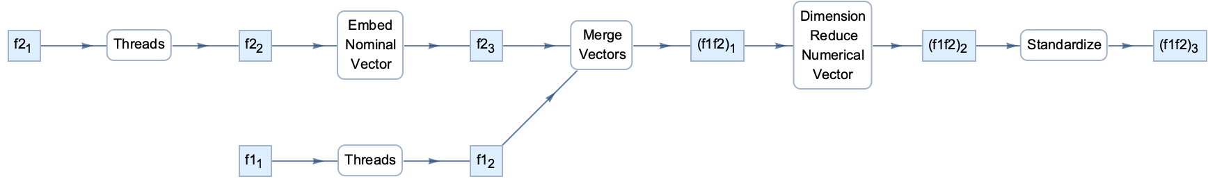
In order to track what happens to individual feature components this will have to be expanded a little, but I believe the current version of the code is already useful for getting some insights.


