Message Boards Message Boards

RotorWith3DEffects modeling problems inconsistent with Mathematica

Posted 2 years ago

This is a question directly related to several other previous questions of mine, however most directly related to Torn Equations

Besides that question, I have also (through Mathematica) modeled, simulated and controlled a flywheel inverted pendulum (youtube link)

This works well, and I have a good mathematical understanding of the model equations, which is why it, and the other previous testbench (as seen in my Torn equations question) are my direct comparisons to models I've made SystemModeler.

When improving my models using RotorWith3DEffects I realized that this particular class isn't quite used as exactly as the other Rotor and also isn't quite connected the same in order to achieve the 1DOF inertia on a 3D body. When reading the documentation there is a single line

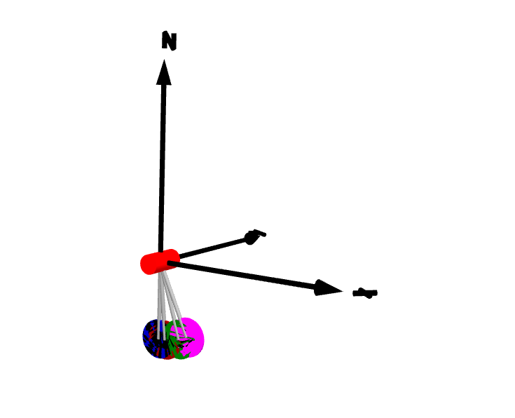
Gyroscopic torques appear, if the vector of the carrier body's angular velocity is not parallel to the vector of the rotor's axis.

Which for my English is a bit cryptic, but fine. When looking at suggested other examples, such as GyroscopicEffects

gryo

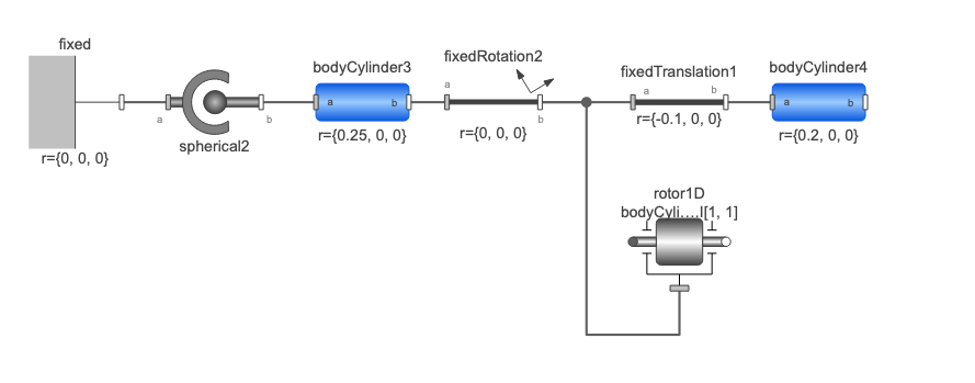
It shows that the class is connected via the Housing connector. So I do this as well in my models, which produce great results that match the real model and the Mathematica version.

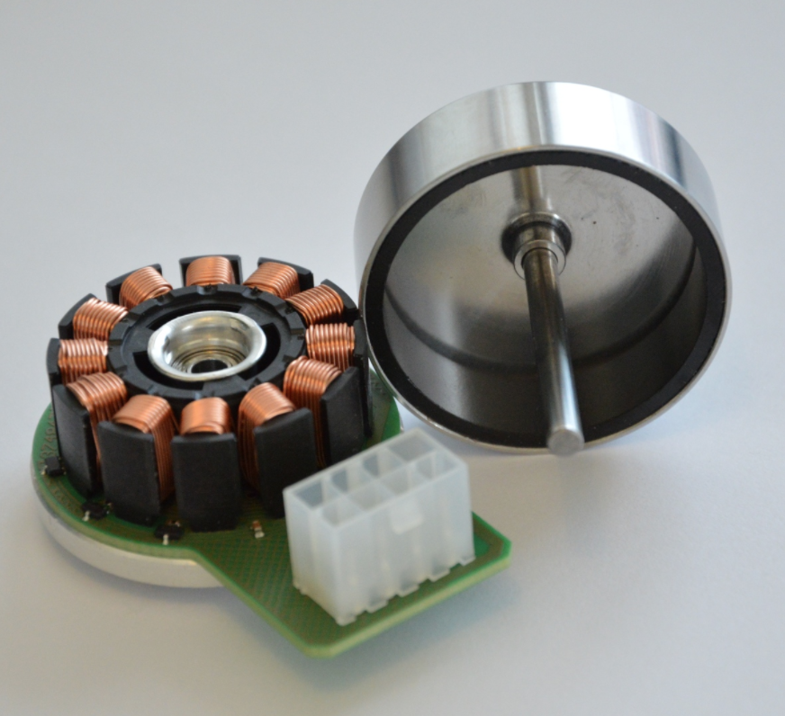
My issue now comes that when trying to improve my BLDC motor model, which is a maxon EC45 Flat, an "aussen roller" Or namely a motor with rotating housing, clearly also has a rotating inertia that I want to include to complete my model.

motor

Because I want to use this in a library/package later for reuse, I want to the motor model to be complete, and not simply add it's inertia to an outside class.

The problem here arises, when I want to connect the motor model shaft of the inner RotorWith3DEffects to an 'shaft' or outer RotorWith3DEffects the gyroscopic effects disappear.

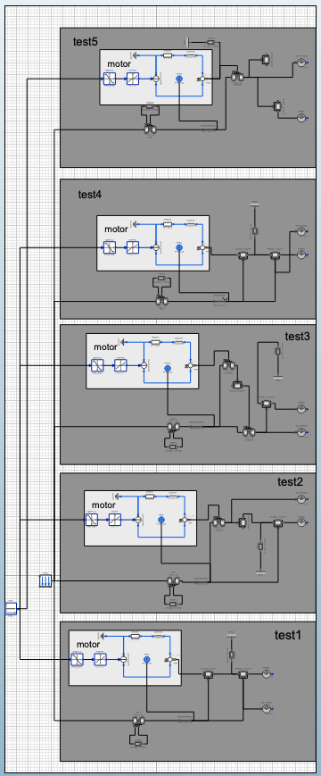
But this is fine, clearly I have a misunderstanding. So I tried to experiment with 5 different modeling/connection techniques to figure out how to connect this model correctly.

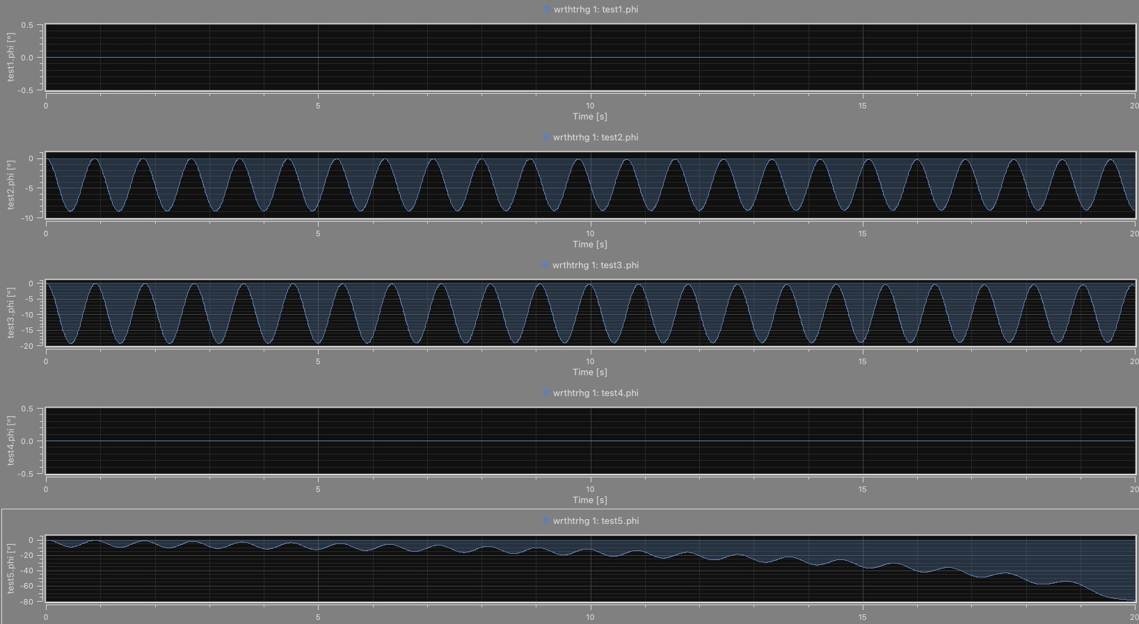
Unfortunately, I now have 5 different results, none of which are similar, and only one that sort of resembles the model from Mathematica, except it appears to have energy being constantly added to the system, instead of it dissipating.

The Mathematica ODEs are :

Where $\alpha(t)$ is the pendulum angle, and $\phi(t)$ is the motor angle. with various inertias, friction and masses.

$$\left\{g \sin (\alpha (t)) (k \text{mw}+l \text{mb})+\text{jw} \phi ''(t)+\Theta \alpha ''(t)=-\text{rb} \alpha '(t)-\mu \tanh \left(\frac{\alpha '(t)}{\iota }\right),\text{jw} \left(\alpha ''(t)+\phi ''(t)\right)=\tau u(t)-\text{rw} \phi '(t)\right\}$$

When given a simple constant input of 0.6 at $u(t)$ from hanging position of initial angle $\alpha(0) = 0$ the Motor spins up, causes swinging and short lived constant offset before the system falls back to angle zero as seen here:

rotor

Also plot

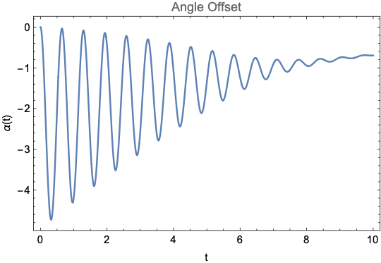
When using the actual physical model, this also happens, pretty much exactly the same, as such I am confident this is modeled fairly well.

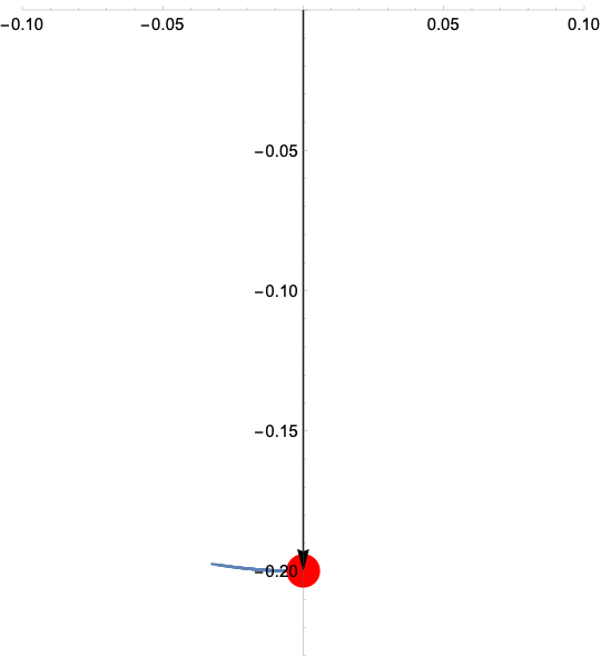
As mentioned unfortunately, when doing this same within my 5 different experiments, I don't get any of the same results but instead either no displacement whatsoever, a constant non-dissipating oscillation or a constant angle accumulation that eventually breaks the simulation, as seen here:

models models more plots

TLDR: I want to be able to use RotorWith3DEffects like Rotor to get gyroscopic effects with my internal motor model, and be able to use the rotors shafts as connection points, rather the housing, however it seems this isn't possible in the way I expect it, and when comparing different connect methods, against Mathematica, I get wildly different results, and I don't know which one is correct, and baring all of them are wrong, then I'm completely stuck.

How do I use this class correctly, the description and one single example within the documentation don't specify this enough for me, and the many test results don't match up with my real world model or Mathematicas.

I have included the Mathematica files and System modeler file within this post for your own testing, done in System modeler 12.3. Thanks for the help.

POSTED BY: Mor Bo
4 Replies
Posted 2 years ago

Thank you Neil For the help and all the explanations. I now have working models with the correct torque exchanges. Greatly appreciate it.

POSTED BY: Mor Bo

Mor,

Motor Modeling

The only reason I mentioned the motor issue is that you had a resistance and inductance but eliminated them (from a dynamics point of view) by forcing current. With the new model, your resistance and inductance now have an effect. Note that the L/R time constant of that motor is approximately 0.0005 (0.5 ms). On the time scales you seem to be considering, it is very fast. This means that you can probably ignore the motor dynamics and remove the resistor and inductor and just command a current to the emf component. Alternatively, you can keep your new, more realistic motor model and control it with your PI controller. The PI controller you designed is very slow for that motor. Your response takes seconds but the motor can respond significantly faster when controlled (I mention this just to help your future modeling efforts). Your current loop bandwidth will be your limiting factor (which depends on your control).

Modeling Inertia

The inertia in the model I provided is behaving correctly. You are commanding torque (i.e. current) to the motor. By changing the inertia of the flywheel or of the motor, you do not significantly change the torque transferred from the motor to the pendulum -- you only affect how fast the rotor accelerates. Torque is Torque -- your control is pushing against a rotating mass to create torque. You command the torque and over a wide range of parameters, you get the torque you command. (To verify this, plot the motor shaft torque and change parameters). That torque then accelerates an inertia, so the larger the inertia the slower the acceleration. BUT the torque is (roughly) the same and the pendulum is "kicked" by roughly the same amount.

However, your instinct is also correct that a larger rotor would swing less! The reason is usually when we significantly increase the inertia, we also increase the weight of the structure -- As I said in my last post, the rotor (and inertia) models do not add non-rotating mass so you would need to model a larger inertia by increasing the inertia AND increasing the pendulum mass. If you increase the mass, THEN, you would get a significant change in the swing due to a given torque. This is the affect you expected to see. To "properly" model this in WSM, I would make my mass be a function of the rotor inertia (or vice-versa) -- there are many equations relating mass and inertia for many different shapes. You can model the rotor as a cylinder and the moving arms sticking out have relatively little mass but relatively lots of inertia. Alternatively, weigh your components and separately estimate or measure the inertia experimentally.

Why the motor should use a flange to attach to the system

The proper way to model a motor mounted on something moving is to have the torque generated between the rotor and the stator. The rotor is free to rotate. The stator tries to rotate but is stopped by the motor mount. To model the affects of this, you need to transfer those torques to the rest of the structure (unless that structure is immovable). When you attach the EMF to ground, those torques are eliminated and you break what you are trying to model. To see this, take a look at how modelica models motors. They extend the "PartialBasicMachine" class which has two inertias, some friction and an optional reaction flange. You need the reaction flange as well.

Why your original model appeared to work

Your original model is doing a strange type of torque transfer. You use an inertia to push back on the motor mount through friction. Because of this you do get a reaction torque and it appears to work. However, it is a flawed model for the motor. Motors do not rely on velocity dependent friction to push on their mounts. They use the torque generated by the emf in the motor to push on the mounts. Your model will alter torque transferred to the mount as a function of rotor speed which is why the inertia magnitude matters in your original model -- However, the inertia should not matter if the motor is modeled in a way that it actually works.

UPDATE: In thinking about my answer, I wanted to clarify why it is not a good physical representation of a motor to have more torque transfer to the base increase as the speed increases. As a mental exercise: run a motor at two different constant speeds. In both cases, the reaction torque (without losses) is zero and no reaction force is passed to the motor mount. With your friction-based torque transfer model, significant, non-zero torque is transferred in both cases, with the higher-speed case transferring more torque. This is non-physical behavior and not a good model for a motor.

I hope this helps

Regards,

Neil

POSTED BY: Neil Singer
Posted 2 years ago

Hello Neil,

Thank you for the explanation and the quick help. I have since improved the motor model to use a PI current controller and a signal voltage... current control

I assume this is what you had meant. Thanks for pointing it out.

I'm still however having a hard time understanding your example model...as far as I can tell, the only reason there is any swinging at all, is because your emf is connected to the axisflange of the Revolute joint, if I remove that connection it fails to swing.

As far as I understand your description, the torque exchange comes from just that RotorWith3DEffects housing connection and the rest is additive, and exchanged into the body through that...Why do you have it also being passed into the Revolute that connects the motor directly to the world joint and not the fixedtranslation where the flywheel and motor are actually mounted? I'm not sure if you saw the prototype youtube video I made, with my actual working prototype, but the way you have it connected, I don't really understand.

It seems the additive effect also isn't correctly accounted for as you mentioned...only by changing the motor inertia J to something else beyond the initial value has an affect on the deflection, when changing your FanBladeInertia to 1 billion for example, nothing happens. changes

I surely must be daft, or seriously missing something. I don't see anything in the documentation for the emf that the housing needs to be connected to anything (though it certainly does make sense physically), nor do I understand why torque isn't being transferred to the Revolute joint, except only when rotation comes from the housing connection, unless it's through the emf.

I have added a suite of tests again for you to see my changes to your example that will hopefully clarify my issues.

On top of that, I have added a fully working simulation of the flywheel pendulum I did some time ago, with the original working simulation, as I had originally mentioned at the beginning of the question before I began attempting to do things better/have these problems, and a modified version, following your design method, which unfortunately produces incorrect results.

This is seen in the plot fairly well, the top being the new form, and the bottom being my original. enter image description here

I greatly appreciate your help looking at all this and putting up with my lack of understanding ;)

Best Regards.

POSTED BY: Mor Bo

Mor,

Your problem is that you want to model reaction torque from your motor but your motor creates no reaction torque. Another problem with your motor is that you give current commands to a current source so the resistance and inductance is ignored. A correct motor model would have a voltage input to the resistance and inductance which creates a current. You then control the current with your controller.

It makes no sense to use two rotors with 3D effects. If you want/need to add inertia to the 3D rotor, you must use a regular inertia -- it will add to the 3D rotor inertia and transmit its forces through the 3D rotor support.

The attached model works (I did not fix your current source on the electrical side). I used a the 3D rotor to get the gyroscopic affects. The 3D inertia should be that of the rotor of the outrunner motor (the outside part). I connected the torque reaction force back to the joint on which the motor is mounted. I gave the motor some mass because I do not believe that the 3D rotor has mass properties -- only gyroscopic torques (but you should verify this). If you attach the motor to another structure, the inertia of what is attached should be a regular inertia (as shown).

I hope this helps,

Regards,

Neil

enter image description here

POSTED BY: Neil Singer
Reply to this discussion
Community posts can be styled and formatted using the Markdown syntax.
Reply Preview
Attachments
Remove
or Discard

Group Abstract Group Abstract