Triggered by a leak in my hot water boiler at home I built a thermal imaging camera using an Arduino and interfacing it with Mathematica. I tried to make up for the "one-pixel-resolution" by using Mathematica's powerful image analysis abilities. This is a work in progress and I would be delighted to get some comments/suggestions from the Community. In this project, I had a lot of help from
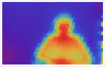
Bjoern Schelter, who has recently joined this Community. If you have the components and use the programs below, you should have a "working" one-pixel thermal camera after 30 minutes or so of DIY. Here's a sneak peek of what we want to get out (this one is a "selfie"):
I use the following components:
- Arduino Uno R3
- MELEXIS / MLX90614ESF-DCI / DS Digital non-contact Infrared Temperature Sensor (~ £35 and more or less the same in USD)
- MG995 Servo Sensor Mount Kit 2 DOF Pan and Tilt Black (~ £24, similar in USD)
- Two 4.7 kOhm resistors.
- One 0.1 uF capacitor.
- One small breadboard.
- 5V power source.
- Wires.
The idea is illustrated in this
Youtube video. To my best knowledge, the original idea comes from a
project of Steffen Strobel in the German science competition "Jugend Forscht". The main idea is to mount a non-contact temperature sensor on a pan and tilt mechanism (i.e. two servos) on a tripod. An Arduino microcontroller is then used to communicate via the serial port with Mathematica, which is used to control the servos and triggers the measurements. After the data acquisition Mathematica cleans the data and produces some thermal images (see below).
We use the following wiring diagram to connect the servos and the temperature sensor to the Arduino.
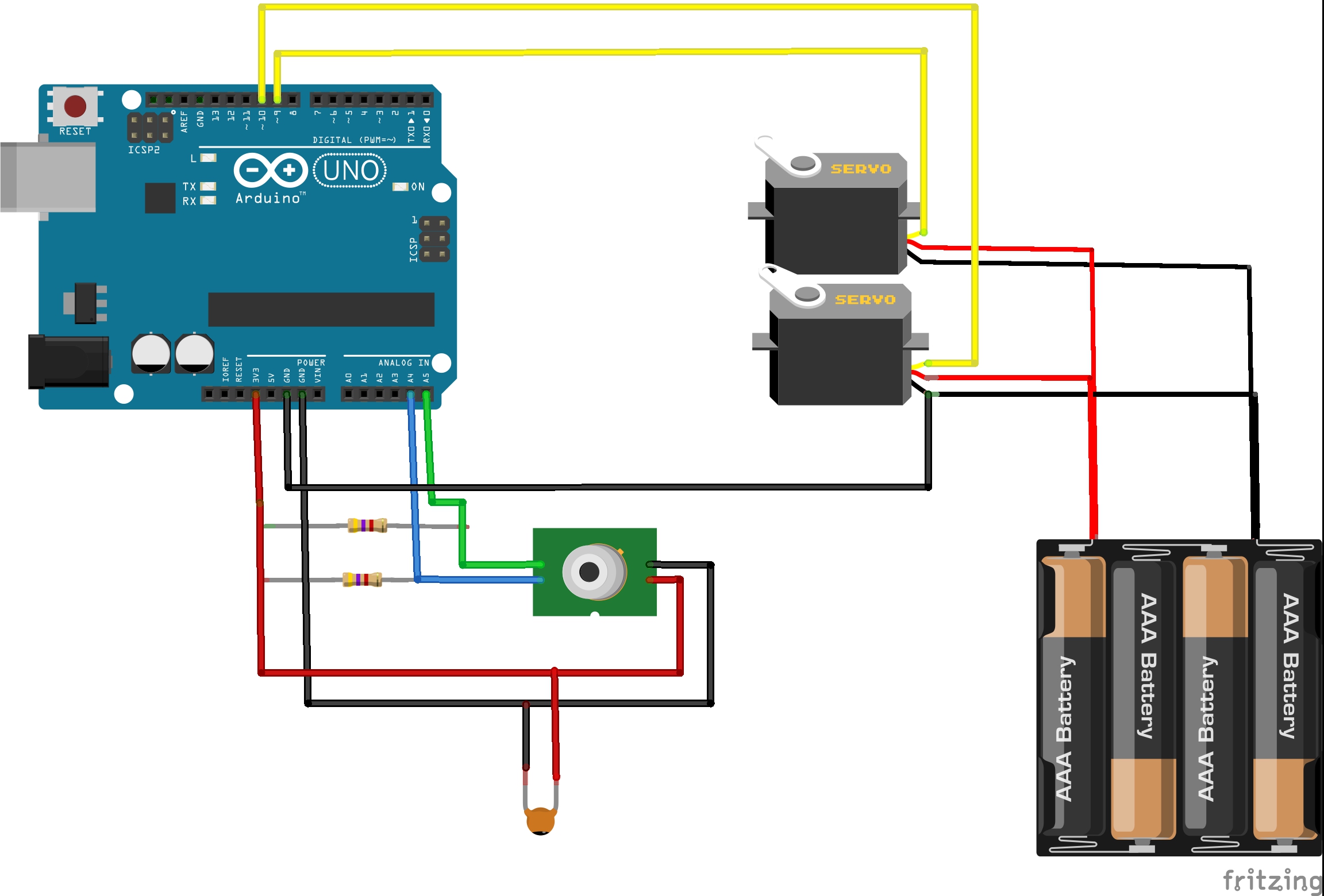
The resistors are 4.7kOhm and the capacitor is 0.1uF. The sensor part is taken from the
bildr.blog, which also shows how to make Arduino talk to the sensor. The Melexis sensor that we chose has a temperature resolution of 0.02 degrees Celsius and a rather narrow field of view, which is important for our application.
For the servo part, we use the standard servo.h library; an example of its application can be found
here.
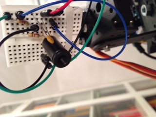
Here is a photo of the sensor/head of the device.
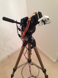
The entire device looks like this.
The idea is to use Mathematica to send instructions to the servos and to initiate the measurements. To interface Mathematica with Arduino we use the
SerialIO package. I found
this website by William Turkel very useful to make SerialIO work on my Mac; following the steps and adapting some directories makes the package work without any problems.
At that point, we have everything in place, and only need to put the bits together. We first need to upload this piece of code (also attached at the bottom) to the Arduino.
#include <i2cmaster.h>
#include <Servo.h>
//Servo setup
int servoPin1 = 9;
int servoPin2 = 10;
Servo servo1;
Servo servo2;
int angle1 = 40; // servo start positions in degrees
int angle2 = 50;
//Melexis setup
int sensor = 0;
int inByte = 0;
void setup()
{
Serial.begin(9600);
// attach pan-tilt servos
servo1.attach(servoPin1);
servo2.attach(servoPin2);
servo1.write(angle1);
servo2.write(angle2);
//Initialise the i2c bus
i2c_init();
PORTC = (1 << PORTC4) | (1 << PORTC5);//enable pullups
establishContact();
}
void loop()
{
if (Serial.available() > 0)
{
inByte = Serial.read();
int dev = 0x5A<<1;
int data_low = 0;
int data_high = 0;
int pec = 0;
i2c_start_wait(dev+I2C_WRITE);
i2c_write(0x07);
// read
i2c_rep_start(dev+I2C_READ);
data_low = i2c_readAck(); //Read 1 byte and then send ack
data_high = i2c_readAck(); //Read 1 byte and then send ack
pec = i2c_readNak();
i2c_stop();
//This converts high and low bytes together and processes temperature, MSB is a error bit and is ignored for temps
double tempFactor = 0.02; // 0.02 degrees per LSB (measurement resolution of the MLX90614)
double tempData = 0x0000; // zero out the data
int frac; // data past the decimal point
// Serial.print(tempData);
// Serial.write(inByte);
// This masks off the error bit of the high byte, then moves it left 8 bits and adds the low byte.
tempData = (double)(((data_high & 0x007F) << 8) + data_low);
tempData = (tempData * tempFactor)-0.01;
//inByte = (float)(((data_high & 0x007F) << 8) + data_low);
float celsius = tempData - 273.15;
sensor=(int)(celsius*100);
//float fahrenheit = (celsius*1.8) + 32;
Serial.print(sensor);
// horizontal "H"-> 72; reverse "R"-> 82; vertical "V"-> 86; end "E"-> 69
if(inByte==72)
{
angle1=angle1+1;
servo1.write(angle1);
}
if(inByte==82)
{
angle1=40;
servo1.write(angle1);
}
if(inByte==86)
{
angle2=angle2+1;
servo2.write(angle2);
}
if(inByte==69)
{
angle1 = 40; // servo back to start
angle2 = 50;
servo1.write(angle1);
servo2.write(angle2);
}
delay(15); // 15 works; wait 15 milliseconds before printing again
}
}
void establishContact()
{
while (Serial.available() <= 0)
{
Serial.print('A');
delay(100);
}
}
The idea is to make Mathematica communicate with the Arduino via the serial connection. The Arduino sketch shows that Ardunio is waiting for instructions, e.g. "H" to move horizontally, "V" to move vertically and "E" to go to the end position.
(*First we load the SerialIO package. See instructions above.*)
<< SerialIO`
(*We test whether Mathematica's applications folder is in the Path. On some Macs Mathematica will be in the /Library directory - used in this example- and in others in the /Users/username/Library directory, where "username" needs to be replaced by the correct user name.*)
MemberQ[$Path, "/Library/Mathematica/Applications"]
(*If this gives True all is fine. If it evaluates to False execute
AppendTo[$Path, "/Library/Mathematica/Applications"]
*)
(*Connect to the Arduino*)
myArduino =
SerialOpen[Quiet[FileNames["tty.usb*", {"/dev"}, Infinity]][[1]]];
SerialSetOptions[myArduino, "BaudRate" -> 9600];
While[SerialReadyQ[myArduino] == False, Pause[0.1]];
(*Data collection, in this case 40 vertical and 70 horizontal pixels; runtime 2-3 minutes; pauses cannot be reduced much further.*)
pixels = {}; SerialRead[myArduino]; For[j = 1, j < 41, j++,
For[i = 1, i < 71, i++, SerialWrite[myArduino, "H"];
AppendTo[pixels, (SerialRead[myArduino] // ToExpression)/100.];
Pause[0.1]]; SerialWrite[myArduino, "R"];
SerialWrite[myArduino, "V"]; SerialRead[myArduino];
Pause[0.1];]; SerialWrite[myArduino, "E"];
(*After the data aquisition close the connection to Arduino*)
SerialClose[myArduino]
(*Now we can use several different ways to represent the data, note that some point at the beginning/end of the scanned lines are removed; there were too many measurements errors just after the "carriage return"*)
ArrayPlot[Partition[Reverse[pixels], 70][[All, 2 ;; -10]],
ColorFunction -> "Rainbow"]
(*here's another colour scheme.*)
ArrayPlot[Partition[Reverse[pixels], 70][[All, 2 ;; -10]],
(*Occasionally there are some outliers in the measurements; here we clean them out.*)
ArrayPlot[
Partition[Reverse[pixels /. x_ /; x > 35. -> 35.], 70][[All,
2 ;; -10]], ColorFunction -> "Temperature"]
ColorFunction -> "Temperature"]
(*This last one uses interpolation to make the image smoother.*)
ListContourPlot[
Partition[Reverse[Log /@ pixels /. x_ /; x > 35. -> 35.],
70][[-1 ;; 1 ;; -1, 1 ;; -10]], AspectRatio -> 0.9,
ColorFunction -> "Rainbow", PlotRange -> All,
InterpolationOrder -> 2, Contours -> 60, ContourStyle -> None]
So here's a photo of my broken boiler and its scan:
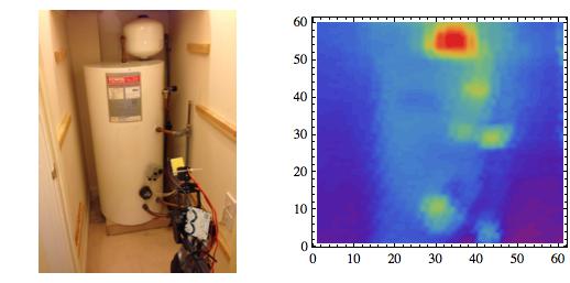
Because of the scanning procedure (which just looks at the angle and does not use any projection), the scan is slightly distorted, but it is possible to recognize the main features and even the sticker on the front!
It appears that this rather primitive device can also be used to analyse electrical components. Here is an image of my MacBook Pro.
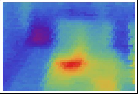
The position of the CPU becomes quite obvious.
There are many things that need to be improved:
(i) First, there is the projection issue. The scanner does scan angles. It needs to be projected to a 2D plane. One might use an ultrasonic distance sensor to get better results.
(ii) The device needs to be calibrated.
(iii) A user interface is needed. It would be useful to click on the image and get the temperature reading.
(iv) The communication between Mathematica and the Arduino need to be improved. The starting position of 40/50 degrees is hard-coded into the Arduino sketch. It should be done by the Mathematica code.
(v) We have not even started to use Mathematica's features on this. Much image processing could be done. The image should be overlayed to a normal photo of the object that is scanned. Manipulate could be used to change thresholds, i.e. the threshold to cut-off outliers, which is currently set to 35 degrees.
(vi) The speed might be improved. I suppose that the scanning time of 3 minutes or so is typical for these devices, but one might improve that a bit. Also, Mathematica could use edge-detection to determine regions where a higher scan density would be helpful to get a better resolution. This only makes sense if the servos could be directed to a certain position much more precisely; alternatively, we could use random positions, which then are precisely determined using an accelerometer or so.
There is of course much more to do. In spite of this being work in progress, I wanted to share this project, and hope for helpful comments.
I attach the Mathematica notebook. I have a movie of the scanning process and the actual arduino sketch which I cannot upload directly. Here are links to the
arduino sketch and the
scanning movie.
M.