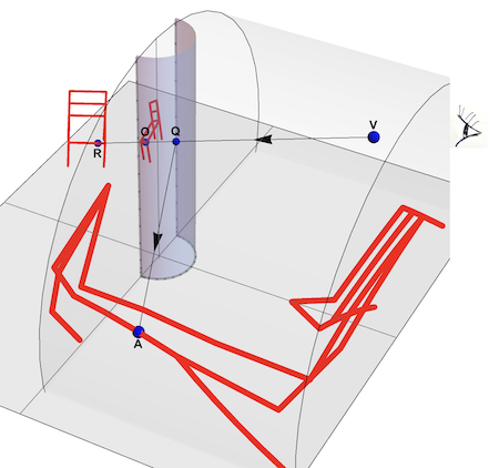
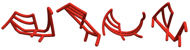
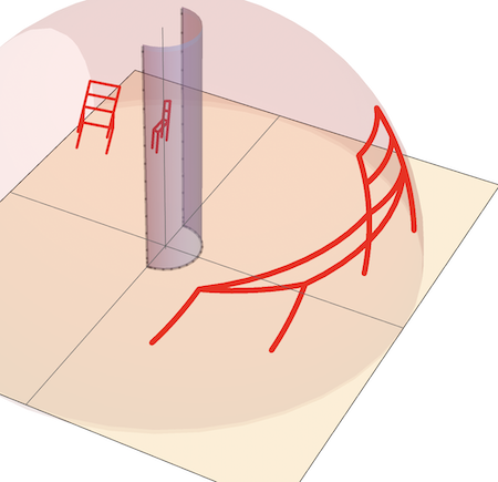
Cylindrical Mirror Anamorphosis is a technique that enables deformed objects to reflect as realistic images in a cylindrical mirror. When observed from the eye position V, a point A on the distorted chair will appear as a point R on the real, undeformed chair. In the illustration above, the distorted chair points A are situated on a horizontal cylinder, but they could also be on a sphere, cone, or any other surface. Interestingly, all points along the HalfLine QA will be reflected as the same point R. The HalfLine QA is the locus of all anamorphic images of R. As an example, below are four examples of anamorphic 3D prints that, when reflected in a vertical cylindrical mirror, appear as an undistorted chair.
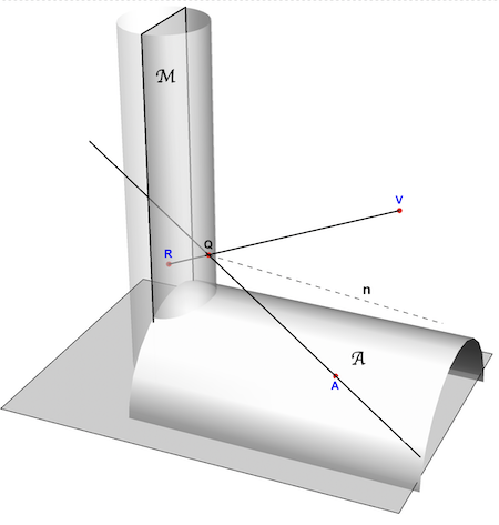
Below, is an arrangement showing anamorphic projection. iThere are two surfaces: The first surface is a mirror, specifically a vertical cylinder denoted as M . The second surface is an anamorphic surface, referred to as A, where the anamorphic image is created . In this case, A takes the form of a horizontal cylinder. The point A represents a location on the anamorphic surface . To understand the process, imagine a light ray emitted from point A . This ray is reflected by the mirror at point Q and ultimately reaches the viewer's eye positioned at V . From the viewer's perspective at V, the point A appears as the reflected point R . The points A and R form an enantiomorph pair : R represents the reflection of A in the mirror surface, while A represents the anamorphic image of R. Any surface can potentially serve as an anamorphic surface, allowing for an infinite amount of deformed anamorphic images. This is a consequence of the fact that all points located on the infinite reflection line QA serve as anamorphic images of R.
The following functions compute all elements needed to convert a reflected point R into its anamorphic image A.
cylinderReflectionPoint computes the intersection point Q of the mirror cylinder with the view-line RV.
cylinderReflectionRay computes the locus (half-line) of all the equivalent anamorphic points of R with regard to V
cylinderAnamorphPoint converts the coordinates of a reflected point ptR to its anamorphic image on the surface anaRegion
cylinderReflectionPoint[ptR : {xi_, yi_, zi_}, ptV : {xv_, 0, zv_}] :=
 NSolve[{{x, y, z} \[Element] HalfLine[{ptR, ptV}] &&
     x^2 + y^2 == 1.}, {x, y, z}][[-1, All, -1]]
cylinderReflectionRay[ptR : {xi_, yi_, zi_}, ptV : {xv_, 0, zv_}] :=
 Module[{ptQ, ptVv},
  (*intersection cyl/viewline*)
  ptQ = cylinderReflectionPoint[ptR, ptV];(*reflection of ptV in n*)
  ptVv = ReflectionTransform[ReplacePart[ptQ, 3 -> 0], ptQ][ptV];
  HalfLine[ptQ, ptQ - ptVv]]
cylinderAnamorphPoint[ptR : {xi_, yi_, zi_}, {xv_, 0, zv_},
  anaRegion_ : InfinitePlane[{0, 0, 0}, {{0, 1, 0}, {1, 0, 0}}]] :=
 First@RegionIntersection[cylinderReflectionRay[ptR, {xv, 0, zv}],
   anaRegion]
A simple chair can be used to demonstrate the above. The function chairPoints computes the coordinates of m points on each section of the chair. The chair can be translated over (xt, yt, zt) and rotated by the angles (phi1, phi2 and phi3) around the coordinate axes.
chair = {
   (*seat*){{{-1, 1, 2}, {-1, -1, 2}}, {{-1, -1, 2}, {1, -1,
      2}}, {{1, -1, 2}, {1, 1, 2}}, {{1, 1, 2}, {-1, 1, 2}}},
   (*sides*){{{-1, 1, 0}, {-1, 1, 2}}, {{-1, -1, 0}, {-1, -1,
      2}}, {{1, -1, 0}, {1, -1, 2}}, {{1, 1, 0}, {1, 1, 2}}},
   (*back*){{{-1, 1, 4}, {1, 1, 4}}, {{-1, 1, 3}, {1, 1, 3}}, {{-1, 1,
       4}, {-1, 1, 2}}, {{1, 1, 4}, {1, 1, 2}}}};
linePoints3D[{ptA : {xa_, ya_, za_}, ptB : {xb_, yb_, zb_}}, m_] :=
 Transpose[{Subdivide[xa, xb, m], Subdivide[ya, yb, m],
   Subdivide[za, zb, m]}]
transfoFun[{phi1_, phi2_, phi3_}, tr : {xt_, yt_, zt_},
   scl : {sx_, sy_, sz_}] :=
  Composition[TranslationTransform[tr],
   RotationTransform[phi1, {1, 0, 0}],
   RotationTransform[phi2, {0, 1, 0}],
   RotationTransform[phi3, {0, 0, 1}], ScalingTransform[scl]];
chairPoints[{phi1_, phi2_, phi3_}, tr : {xt_, yt_, zt_},
  scl : {sx_, sy_, sz_}, m_ : 10] :=
 Module[{chairPts}, chairPts = Map[linePoints3D[#, m] &, chair, {2}];
  Map[transfoFun[{phi1, phi2, phi3}, tr, scl], chairPts, {3}]]
If we look at the chair, we see it as an "observed" 2D image in a plane perpendicular to our view direction. The function observedPoint will convert the 3D chair point by point into a 2D image in the y-z plane if observed from a view point at (xv, 0, zv):
observedPoint[ptR : {xr_, yr_, zr_}, ptV : {xv_, 0, zv_}] :=
 Quiet@First[
   NSolveValues[
    Element[{x, y, z}, InfiniteLine[{ptR, ptV}]] && x == 0, {x, y, z}]]
pts = chairPoints[{0, 0, 55 °}, {-1.5, 0, 0}, {.8, .8, .8}];
observedChairPts =
  ParallelMap[observedPoint[#, {10, 0, 5}] &, pts, {3}];
Graphics3D[{(*floor*){Opacity[.5],
   InfinitePlane[{0,
     0, -.01}, {{0, 1, +.01}, {1, 0, -.01}}]}, {Opacity[.25],
   InfinitePlane[{0, 0, 0}, {{0, 0, 1}, {0, 1, 0}}]}, Red,
  Map[Tube[#, .035] &, pts, {2}], {AbsoluteThickness[4],
   Map[Line, observedChairPts, {2}]}}]
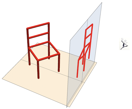
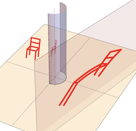
The provided functions offer a versatile way to show various anamorphic deformations of objects (such as a chair) by employing different anamorphic surfaces. Let's start with a vertical plane:
Module[{xv = 5, zv = 5, phi1 = -15 °, phi2 = 0, phi3 = 10 °, dx = -2,
  dy = -.4, dz = 1.75, chairPts, observedPts, anaSurface, anaPts},
 chairPts =
  chairPoints[{phi1, phi2, phi3}, {dx, dy, dz}, .8 {1, 1, 1}, 10];
 observedPts =
  ParallelMap[observedPoint[#, {xv, 0, zv}] &, chairPts, {3}];
 anaSurface = InfinitePlane[{4, 0, 0}, {{0, 0, 1}, {.25, 1, 0}}];
 anaPts =
  Map[cylinderAnamorphPoint[#, {xv, 0, zv}, anaSurface] &,
   observedPts, {3}];
 Graphics3D[{(*floor*){Opacity[.5],
    InfinitePlane[{0, 0, -.01}, {{0, 1, +.01}, {1, 0, -.01}}]}, Red,
   (*chair*){AbsoluteThickness[3], Map[Line, chairPts, {2}]},
   (*observed chair*){AbsoluteThickness[1],
    Map[Line, observedPts, {2}]},
   (*anamorphic chair*){AbsoluteThickness[4],
    ParallelMap[Line, anaPts, {2}]},
   Opacity[.25], mirror[[1]], Opacity[.1], anaSurface}]]
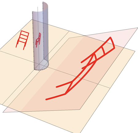
Replacing the anaSurface with an inclined horizontal plane:
The anaSurface can be replaced with any developable surface such as a cylindrical or conical surface:
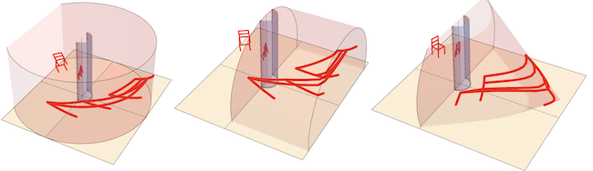
or un-developable (spherical) surface :
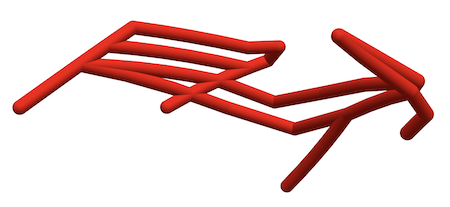
To speed up the computations, we used thick lines for the 3D graphics of the chair. Those who own a 3 D printer can print the anamorphic chair by replacing Line with Tube as in the example code below:
Module[{xv = 6, zv = 6, ptV, chairPts, observedPts, anaSurface,
  anaPts},
 ptV = {xv, 0, zv};
 chairPts =
  chairPoints[{10 °, 10 °, 30 °}, {-2, -.35, 3}, .95 {1, 1, 1}, 5];
 observedPts =
  ParallelMap[observedPoint[#, {xv, 0, zv}] &, chairPts, {3}];
 anaSurface = Cylinder[{{0, 0, 1}, {7, 0, 1}}, 6];
 anaPts =
  Map[Last@cylinderAnamorphPoint[#, {xv, 0, zv}, anaSurface] &,
   observedPts, {3}];
 chair3D = Graphics3D[
   {Red, AbsoluteThickness[8],
    ParallelMap[Tube[#, .2] &, anaPts, {2}]},
   Boxed -> False]]
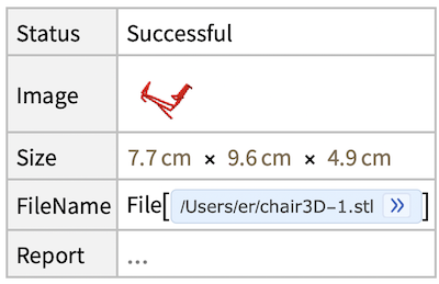
Printout3D[chair3D, "chair3D-1.stl"]
 Attachments:


