Message Boards Message Boards

0
|
7318 Views
|
5 Replies
|
1 Total Likes
View groups...
Share
Share this post:
GROUPS:

Creating Supports in SystemModeler ....

Posted 11 years ago

I'm slowly grinding through the tutorials in the getting started guide and would like to try and build on the chain link pendulum example.

Firstly I tried to fix the end of the pendulum, so that the chain would drape. Screenshot of my model below.
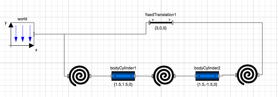
Chain pendulum with attempt to fix one end

Then my second goal is to create a horizontal roller support, so that the rotational springs could hold it in position through their rotational stiffness.

I'd genuinely appreciate any guidance on how to create a horizontal roller, or create multiple support points.

*The spirals are revolute joints, with springs and dampeners attached. If I remove the fixed translation component, the model functions quite happily as a chain pendulum.

All help gratefully received.

POSTED BY: Neil
5 Replies
Posted 11 years ago

I see. You can modify my above model slightly: three multibody bars connected with revolute joints

This will generate a simulation that looks like this: 3D multibody animation of horizontal support

You can add forces with the Modelica.Mechanics.MultiBody.Forces library.

POSTED BY: Johan Rhodin
Posted 11 years ago

Hi Neil,

Not sure what you want to accomplish. Can you show a picture or a sketch of the system or mechanism that you are trying to model?

Here's a model with two supports:

Two supports in a multibody model

Animation:

Horizontal support system

POSTED BY: Johan Rhodin
Posted 11 years ago

Thanks for the response.

What I'd like to create are two supports, with a prescribed distance between them.

Between these two supports will be a series of links, whose total combined length would be greater than the distance between the supports.

Using revolute joints between each link, I would like to model the links so they drape between the two supports under their selfweight.

The idea being that I could reverse the geometry, include rotational springs on the revolute joints and make a springy arch that can support loads, with its load carrying capacity being driven by the stiffness of the springs.

I hope this makes sense, I'm not near a scanner for a few days else I would draw a sketch.

POSTED BY: Neil
Posted 11 years ago

Diagram below of what I would like to achieve as a system, once stable I would like to place forces and/or accelerations to the red nodes.

enter image description here

I hope this makes sense...

POSTED BY: Neil
Posted 11 years ago

Brilliant, thank you very much. It was the addition of the special revolute joint at the end to prevent it being a planar loop that was eluding me.

POSTED BY: Neil
Reply to this discussion
Community posts can be styled and formatted using the Markdown syntax.
Reply Preview
Attachments
Remove
or Discard

Group Abstract Group Abstract