When building complex systems---especially in automotive, energy, or industrial domains---we often run hundreds of simulations to validate performance across real-world conditions. But running simulations alone isn't enough.
Traditionally, engineers use Design of Experiments (DOE) to:
- Systematically vary inputs (e.g., temperature, load, environment)
- Observe system responses
- Use statistics to identify sensitivities and optimize performance
That's useful---but DOE alone doesn't tell you if your model meets formal specifications under every scenario.
This article is about going beyond DOE:
- Automating large-scale simulations (DOE-style configuration space)
- Applying formal, symbolic validation criteria
- Using visual diagnostics and even LLMs to generate engineering insights
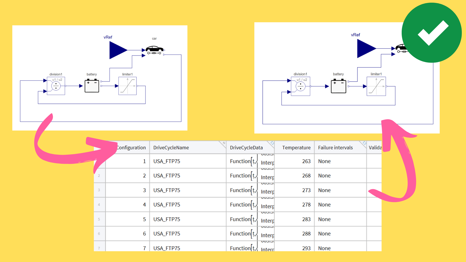
Case Study: Validating an EV Battery Model
Suppose we're designing an electric vehicle. One requirement is:
Battery current must never exceed 100 A, across all drive cycles.
We simulate the model across 12 standard drive cycles, similar to a DOE-style input sweep, and automatically verify the spec using symbolic logic:
Let's import the configurations:
configurations = CloudImport[
CloudObject["https://www.wolframcloud.com/obj/ankitn/configurations"]]
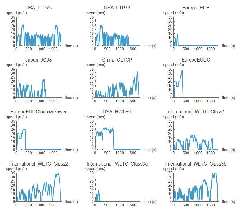
Plot the drive cycles:
plots = Table[
   Plot[configurations[[i, 3]][t], {t, 0, 1800},
    PlotRange -> {Automatic, {0, 35}},
    PlotLabel -> configurations[[i, 2]],
    AxesLabel -> {"time (s)", "speed (m/s)"}], {i, 1,
    Length[driveCyclesNames]}];
GraphicsGrid[ArrayReshape[plots, {4, 3}]]
Validate against the requirement:
currentValidation = SystemModelValidate[
  "CarDriveCycleTest",
  SystemModelAlways[t, "battery.i"[t] < 100],
  <|
   "Inputs" -> {"vRef" -> Normal@configurations[[All, "DriveCycleData"]]},
   "MaxFailureIntervals" -> Infinity
   |>
  ]
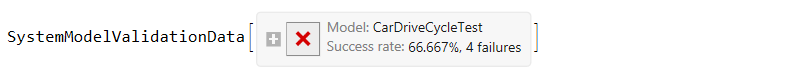
The requirements fail for 4 drive cycles.
Let's plot the failure scenarios. We begin by extracting the failure configurations.
failureConfigurations = currentValidation["AllFailureConfigurations"];
failurePositions =  currentValidation["AllFailureConfigurationsPosition"];
Then simulate and plot the scenarios that failed:
plotFun = SystemModelPlot["CarDriveCycleTest", {"battery.i"},
 #1, PlotLabel -> #2, PlotRange -> {Automatic, {-50, 150}}, ImageSize -> 325] &;
simPlots = MapThread[plotFun, {failureConfigurations, driveCyclesNames[[failurePositions]]}];
Obtain failure plots:
failurePlots = Show[#, ImageSize -> 450] & /@ Normal@currentValidation["FailurePlot"][[All, 2]];
Merge the simulation plot with the failure plots and observe the results:
mergedPlots = GraphicsColumn[{simPlots[[#]], failurePlots[[#]]},
     ImageSize -> Large, Alignment -> Left] & /@ Range[Length[failurePlots]];
GraphicsGrid[ArrayReshape[mergedPlots, {2, 2}]]
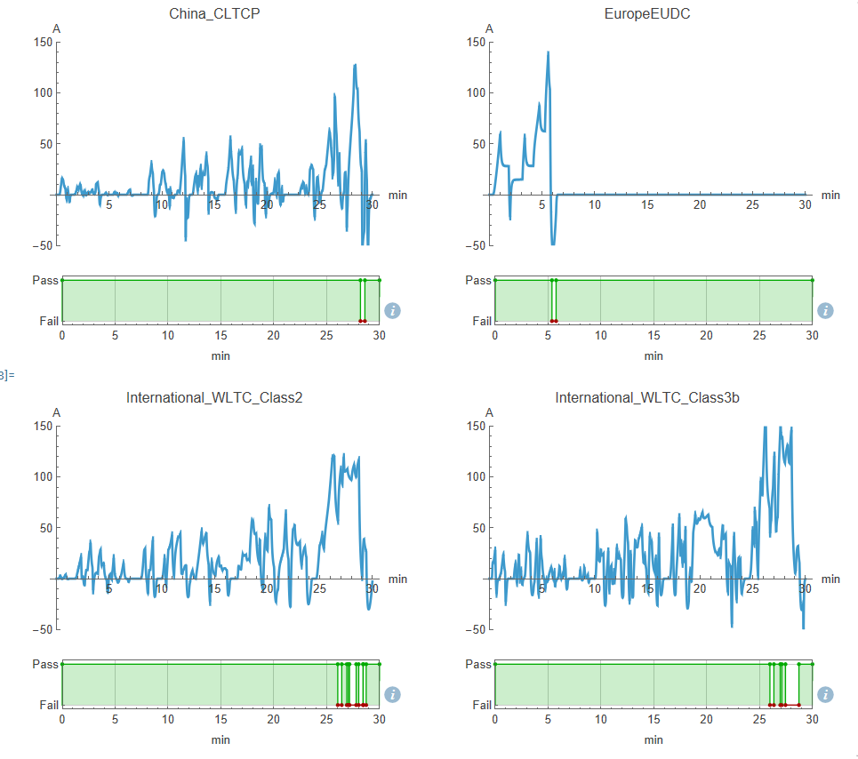
In this test:
- Success rate: 66.67%
- Failures: 4 scenarios
- Drive cycles like ChinaCLTCP and WLTCClass3b triggered violations.
You don't just get a pass/fail---you get visual diagnostics:
- Time-series plots of failure points
- Highlighted intervals where specs were violated
- Direct links to model inputs
Thermal Window Constraint
A second requirement:
Battery temperature must not remain above 25°C for more than 3.5 minutes.
We simulate the model across a matrix of:
- Ambient temperatures (263 K to 303 K)
- Drive cycles
That's a classic DOE matrix---but here's how we layer validation:
{temperatures, driveCyclesRef, driveCyclesName} =
  Transpose@Flatten[Table[Table[{i, driveCyclesData[[j]], driveCyclesNames[[j]]},
{i,Range[263, 303, 5]}], {j, Length@driveCyclesData}], 1];
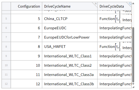
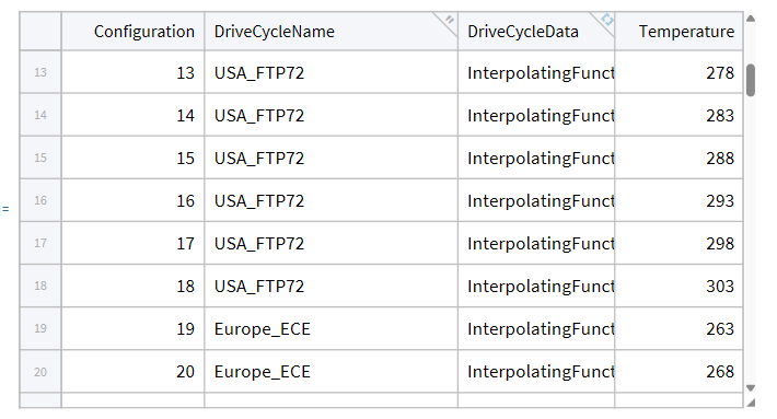
We can now create the configuration table:
thermalConfigurations = Tabular@Join@Table[
<|   "Configuration" -> i,
     "DriveCycleName" -> driveCyclesName[[i]],
     "DriveCycleData" -> driveCyclesRef[[i]],
     "Temperature" -> temperatures[[i]]
|>,
 {i, Length@temperatures}]
Simulate across the 108 variations and validate the results:
sims = SystemModelSimulate[
   "ThermalManagement.BatteryThermal",
   <|
    "Inputs" -> {"vRef" -> Normal@thermalConfigurations[[All, "DriveCycleData"]]},
    "ParameterValues" -> {"T" -> Normal@thermalConfigurations[[All, "Temperature"]]}
    |>
   ];
temperatureValidation = SystemModelValidate[
      sims,
      SystemModelAlways[t, 300 <= t, !SystemModelSustain["temperatureSensor.T"[t] > 25, Quantity[3.5, "Minutes"], Infinity}]],
  <|
   "MaxFailureIntervals" -> Infinity
   |>
  ]

Result:
- 108 total simulations
- 87.96% pass rate
- 13 failures, mostly in high-temp conditions (e.g., China_CLTCP @ 288K)
Let's plot one failure scenario:
firstFailureConfig =
 Normal@thermalConfigurations[[All, {"DriveCycleName",  "Temperature"}]][[temperatureValidation["AllFailureConfigurationsPosition", 1]]];
simPlot =
 SystemModelPlot[
  "ThermalManagement.BatteryThermal",  {"temperatureSensor.T"}, temperatureValidation["AllFailureConfigurations", 1],
  PlotLabel -> StringJoin[firstFailureConfig["DriveCycleName"], " & ", ToString[firstFailureConfig["Temperature"]], " K"], PlotRange -> All, ImageSize -> 350];
failurePlot = Show[Normal@temperatureValidation["FailurePlot"][[1, 2]], ImageSize -> 375];
GraphicsColumn[{simPlot, failurePlot}, ImageSize -> Medium, Alignment -> Left]
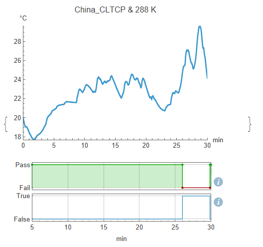
This test doesn't just record temperature - it asserts compliance with a thermal durability spec.
LLM-Assisted Post-Processing
Traditional DOE stops at generating plots and statistical metrics.
With structured failure data and symbolic specs, we now feed:
- Model documentation
- Simulation configs
- Validation results
- Failure intervals
...into a prompt for a language model, which returns a full engineering summary that can be shared with others.
Summary includes:
- Model composition summary
- Validation requirements
- Clear pass/fail reporting by config
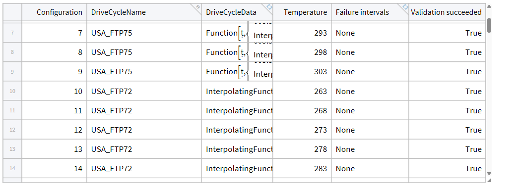
Create an extended table by adding validation results columns to the configuration table.
validationResultColumn =
  Table[If[MemberQ[temperatureValidation["SuccessConfigurationsPosition"], i],True, False], {i, Length[sims]}];
intervalColumn =
  Module[{n}, n = 0; Table[If[MemberQ[temperatureValidation["AllFailureConfigurationsPosition"], i], n = n + 1; temperatureValidation["FailureIntervals", n], None], {i, Length[sims]}]];
configWithValidation = InsertColumns[
  configurations,
  {
   "Failure intervals" -> intervalColumn,
   "Validation succeeded" -> validationResultColumn
   }
  ]
 Pass on the model data and the validation results to the LLM to generate a summary:
configLLM = Normal@configWithValidation[[All, {"Configuration", "DriveCycleName", "Temperature", "Validation succeeded", "Failure intervals"}]];
modelData = createChunk["BatteryThermal"];
reqQuery =  "the battery must not stay above 25°C for more than 3.5 minutes-a thermal stress requirement.";

LLMSynthesize[
 {
  "Create an engineering summary",
  "model information ->", ToString@modelData,
  "validation query ->", ToString@reqQuery,
  "results ->", ToString@configLLM
  }
]
Here is the LLM response:
Engineering Summary: Battery Thermal Management Model
Model Overview
The Battery Thermal Management Model, named BatteryThermal, is designed to simulate and manage the thermal behavior of a battery system in an electric vehicle. It includes various components that regulate heat transfer and flow, ensuring the battery remains within safe operating temperatures to prevent thermal stress.
Key Components
Heat Transfer Elements:
- Convection: Simulates convective heat transfer around the battery.
- Temperature Sensor: Monitors the temperature of the battery.
- Prescribed Heat Flow: Drives thermal flow based on specified conditions.
Fluid Dynamics
- Ambient: Represents the surrounding temperature and conditions.
- Pump: Circulates a coolant fluid (Glycol 20% solution) through the thermal management system.
- Pipe Components: Facilitate fluid flow and heat exchange, with defined properties for laminar flow and pressure drops.
Control Components:
- PID Controller: Regulates temperature based on sensor readings and reference values.
- Filter: Stabilizes the control input to ensure robustness against noise.
Battery and Motor Elements:
- Battery Power: Represents the battery's heat generation and operational status.
- Motor and Gear: Integrated with the battery model to simulate the thermal impact of load and energy demands.
Validation Objectives
The system's critical validation requirement is to ensure that the battery does not exceed 25°C for more than 3.5 minutes during operation in various drive cycles. This thermal stress limit is essential for maintaining battery longevity and safety.
Results Summary
Validation tests were conducted across multiple configurations and drive cycles, including:
Drive Cycles Tested:
- USA FTP75
- Europe ECE
- Japan JC08
- China CLTCP
- International WLTC
Validation Success:
- Successful validation across most configurations indicating that temperatures remained within acceptable limits.
- Notable exceptions where thermal limits were exceeded in configurations 42, 43, 44, and 45 during the China CLTCP drive cycle.
- Results indicate consequent failure intervals where the battery exceeded the specified thermal limits.
Conclusion
The BatteryThermal model effectively simulates and controls the battery's thermal management in electric vehicles under a variety of operating conditions. While most scenarios validate successfully, specific conditions indicate a need for further optimization in managing thermal loads to ensure adherence to critical temperature limits. Continuous refinements and additional exploratory simulations are recommended to enhance thermal performance and reliability."
Why This Matters
Design of Experiments is great for:
- Understanding behavior
- Running structured simulations
- Informing design choices
But when your system must meet strict specs under all conditions, you need more.
Symbolic model validation bridges the gap:
- DOE-style input space
- Spec-driven logic
- Automation at scale
- LLM-assisted reporting
This let's be go beyond "run and plot"---to industrial-strength design validation.
Final Thought
Model validation isn't just a checklist item. It's a design exploration tool, a debugging accelerator, and a spec compliance engine.
And when you validate at scale---across 1000+ simulations with formal specs---you don't just catch problems. You shape better designs.
 Attachments:


