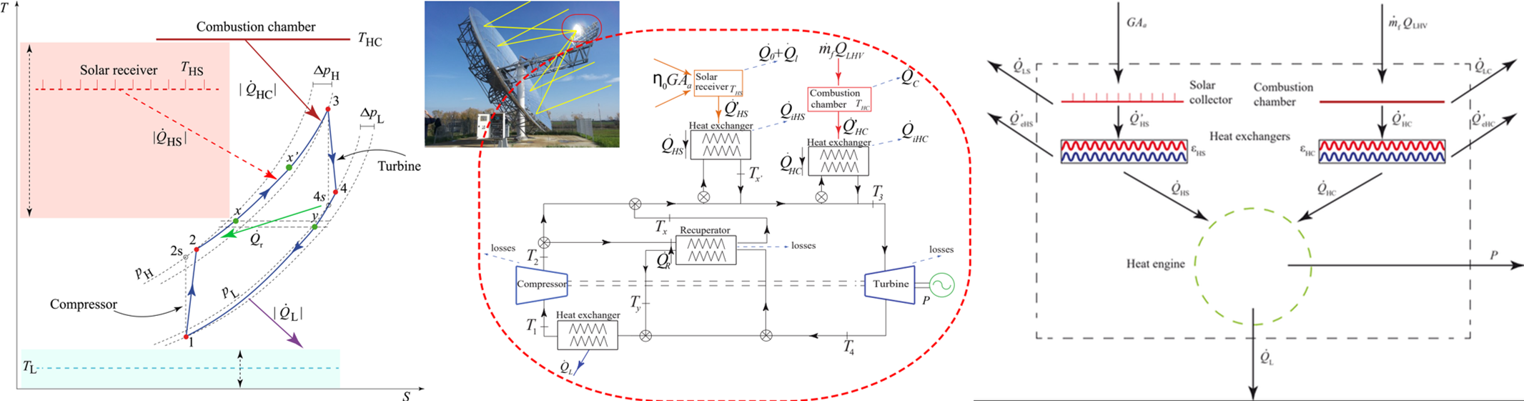
Fig 1 (left): T-S diagram for a closed recuperative Brayton cycle performed by the MGT
Fig 2 (center):Scheme of the thermosolar hybrid plant composed by a solar subsystem (collector,solar receiver and heat exchanger) a combustion chamber (together with its heat exchanger) and the micro-gas turbine as power block.η0 stands for the optical efficiency (ηopt within this manuscript) and G represents DNI value.
Fig 3 (right): Scheme of the energy flows involved in the hybrid cycle
 Attachments:


