Message Boards Message Boards

2D Unconfined Compression with FEM

Posted 10 years ago

I've recently started using both Mathematica and the Finite Element Method. To familiarize myself with both, I've been trying out some things based on the examples provided. In one of the tutorials, they show how to simulate bending of a beam using plane stress (it can be found under "FEMDocumentation/tutorial/SolvingPDEwithFEM"). I figured this example can be modified to be used for a compression instead, but the results confuse me. The code I used is:

Needs["NDSolve`FEM`"]

(*Plane Stress Operator*)
op = {Inactive[
       Div][({{0, -((Y \[Nu])/(1 - \[Nu]^2))}, {-((Y (1 - \[Nu]))/(
           2 (1 - \[Nu]^2))), 0}}.Inactive[Grad][
         v[x, y], {x, y}]), {x, y}] + 
     Inactive[
       Div][({{-(Y/(1 - \[Nu]^2)), 
          0}, {0, -((Y (1 - \[Nu]))/(2 (1 - \[Nu]^2)))}}.Inactive[
          Grad][u[x, y], {x, y}]), {x, y}], 
    Inactive[
       Div][({{0, -((Y (1 - \[Nu]))/(2 (1 - \[Nu]^2)))}, {-((
           Y \[Nu])/(1 - \[Nu]^2)), 0}}.Inactive[Grad][
         u[x, y], {x, y}]), {x, y}] + 
     Inactive[
       Div][({{-((Y (1 - \[Nu]))/(2 (1 - \[Nu]^2))), 
          0}, {0, -(Y/(1 - \[Nu]^2))}}.Inactive[Grad][
         v[x, y], {x, y}]), {x, y}]} /. {Y -> 10^3, \[Nu] -> 25/100};

(*Boundary Conditions*)
Subscript[\[CapitalGamma], 
  D] = {DirichletCondition[v[x, y] == 0., y == 0], 
   DirichletCondition[v[x, y] == -0.1, y == 1]};

(*Solution*)
{uif, vif} = 
  NDSolveValue[{op == {0, 0}, Subscript[\[CapitalGamma], D]}, {u, 
    v}, {x, 0, 5}, {y, 0, 1}];

(*Visualisation*)
mesh = uif["ElementMesh"];
Show[{
  mesh["Wireframe"[ "MeshElement" -> "BoundaryElements"]],
  ElementMeshDeformation[mesh, {uif, vif}][
   "Wireframe"[
    "ElementMeshDirective" -> Directive[EdgeForm[Red], FaceForm[]]]]}]

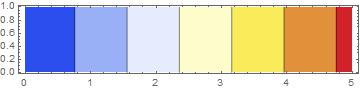
ContourPlot[uif[x, y], {x, 0, 5}, {y, 0, 1}, 
 ColorFunction -> "Temperature", AspectRatio -> Automatic]

The graphs this produces are as follows:

Construct Deformation

Deformation Contour Plot

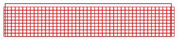
The result is indeed a 10% compression as indicated by the boundary conditions. However, wouldn't one expect the sides to both have an equal lateral deformation? As it is now, the construct is mainly deformed to the right. Did I make some mistake in the code or am I misunderstanding something about the theory behind solid mechanics?

POSTED BY: Dave Wanders
4 Replies
Posted 10 years ago

Ah right, that makes sense. I also just realized that, since these constructs are often cylindrical and axisymmetrical type plugs, I can set the deflection in the x direction to zero for x == 0, which seems to solve the problem.

POSTED BY: Dave Wanders

I don't think you need to build another FEM code from scratch. It appears to me that Mathematica V10 is already a capable infrastructure for FEM, although we should continue to push the developers for improvements, and better documentation.

Your example is a coupled set of equations, with one variable lacking the required boundary conditions to specify a unique solution for it. There is always error in finite element solutions, arising from many causes, and since your X and Y solutions are coupled, error in one variable can creep into the other, causing the sort of problem you have identified.

The solution here is to take care when setting boundary conditions. They are just as important as meshing, material properties, and loads in getting sensible results from the finite element method. In your biomaterials research, you might want to use special purpose interface elements, that mimic soft or yielding joints between stiffer parts of a model. I don't know how, or even if its possible, to create custom interface elements in V10. It would be interesting if someone would comment on that.

Posted 10 years ago

Thank you for your reply! Strange that it gives these random x deformations. And a shame that it is unclear why this happens. The area I will want to apply it to is cartilage tissue engineering and I'm not sure on what exactly happens at these surfaces when compressing it. I expect that there will be very little friction between bottom surface/indenter and the cartilage. Maybe I'm wrong though and I can set the deflections in the x direction to zero for both the top and the bottom of the construct.

Is it likely that this problem would be solved by building the FEM method from the ground up? So using the functions of Mathematica to define the transformation of the PDEs, discretization, forming a linear set of equations, etc. If I have the time I might try and do that instead, but only if it would resolve these problems of course.

POSTED BY: Dave Wanders

You have not applied any boundary conditions on deflections in the x direction. I am not sure why, but most FEM codes given this identical problem specification will produce random unphysical x deformations, like you have seen. The fix is to apply an X fixity. If you insert something like:

DirichletCondition[u[x, y] == 0., y == 0]

to your list of Boundary conditions, then as you expected, the X deformations will be nicely symmetric, and show the effect of the Poisson Ratio.

Deformed Elements with x fixity on bottom

X Deformation with x fixity on bottom

Reply to this discussion
Community posts can be styled and formatted using the Markdown syntax.
Reply Preview
Attachments
Remove
or Discard

Group Abstract Group Abstract