Message Boards Message Boards

Router and LAN visualization (graph)

Posted 10 years ago

Hi!

I'm trying to create network map, using Mathematica. As input I have information about all links on the network, including port numbers, speed, etc. The main task is just visualization of this data.

Network equipment divided by network's layers: core, aggregation and distribution (or similar). Nodes on each part of network are known and must be respectively displayed (with different color, image, as example).

Now I'm trying to display link table with ports and speed, but can't correctly display labels on edges: can't correctly place port's numbers at start end of edge - they intersect with node image.

As result would like to get something like this, but with signed ports on links: enter image description here
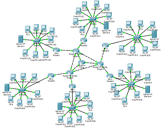
Can anybody help me with this? I'm totally newbie in Wolfram Math :( Input data can be preformed as you wish.

POSTED BY: Quemy Yrwn
7 Replies
Posted 10 years ago

Interesting problem, but please post a sample of the data.

POSTED BY: Gustavo Delfino
Posted 10 years ago

Format like this:

node1,node2,p1,p2,10g

node3,node4,p4,p8,1g

means that node1's p1 connected to the node2's p2 with 10g link; node3's p4 connected to the node4's p8 with 1g link.

And a lot of strings like this in file. File is generated by bash script by processing equipment's topology table (running configuration or other's) and can add there anything else, including Wolfram's operators and constructions.

POSTED BY: Quemy Yrwn

I would not try to put to much text in this picture. The original you're showing is already crowded and when it's getting larger it will be useless.. Why not using colors for the "speed" of the edges. Eg 1Gb on black, 10Gb on red etc. What I've done a while back (lost the code :( ) is to create a list of node types. Then you can color the vertices according to the type (servers,routers,switches,core routers etc). The labels (MM9) was a bit though to get them readable due to the layout algorithms that MM uses.

POSTED BY: l van Veen
Posted 10 years ago

Yeah, edge color will be used, but not for speed. It will represent optical link type: MMF, SMF with different parameters (around 5 types at all). Display link speed is really unnecessary, but ports are (on green circle's places on picture above). Link speed can be represented by edge width...

POSTED BY: Quemy Yrwn

Interesting question, but is there a reason you do not post "your trouble image" so people can clearly see what is wrong? And the code - so they can use it and try to fix it. The more specific is the question the more specific help you will get. General questions inspire general advice.

POSTED BY: Sam Carrettie
Posted 10 years ago

Okey, but code is not full. As input:

  1. edges = {"824-3" <-> "205-11"}

2 style = {

VertexShape->...image ommited...,

VertexLabels->Placed["Name",{1/2,0.85}],

ImageSize->1000

}

Output: Graph[edges,style]

Next I add labels by example at start, middle and end of line (sorry, can't fine documentation page - there is an example with positioning of 3's labels on graph's edge) and by experement understood, that node image intersect and covers labels at "start" and "end" of edge.

POSTED BY: Quemy Yrwn
Posted 10 years ago
edges = {
  Labeled["Node 1" <-> "Node 2", 
   Placed[{"port 1", "link", "port 2"}, {"Start", "Middle", "End"}]]
  };
style = {
  VertexShape ->image,
  VertexLabels -> Placed["Name", {1/2, 0.85}],
  ImageSize -> 1000
  };
Graph[edges, style]

Code

As you can see, edge labels and node's images overlaps. And I don't know how to fix it...

POSTED BY: Quemy Yrwn
Reply to this discussion
Community posts can be styled and formatted using the Markdown syntax.
Reply Preview
Attachments
Remove
or Discard

Group Abstract Group Abstract