Message Boards Message Boards

0
|
8346 Views
|
5 Replies
|
0 Total Likes
View groups...
Share
Share this post:

How to plot a projection of parallelepiped?

Hi!

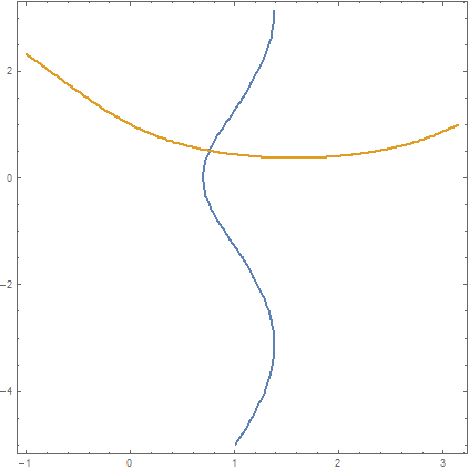
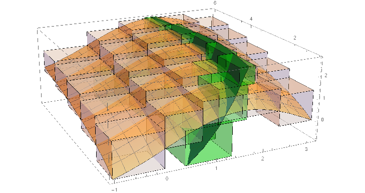
I've got a graphs of system of equations and parallelepipeds on it.enter image description hereenter image description here Tell me, please how to plot a projection of parallelepipeds?
l = Plot3D[Sin[x] + Log[y], {x, -1, 3.14}, {y, 1, 6}, 
   PlotStyle -> Opacity[0.7]];
e = Plot3D[Cos[y] + Exp[x] - 3, {x, -1, 3.14}, {y, 1, 6}, 
   ColorFunction -> "DarkRainbow"];

(*l1=Graphics3D[{Opacity[0.9],Parallelepiped[{-1,-1,0},{{7,0,0},{0,3,\
0},{0,0,5}}]},Axes\[Rule]True]*)
l1 = Graphics3D[{Opacity[0.3], 
    Parallelepiped[{-1, 
      1, -0.85}, {{1, 0, 0}, {0, 1, 0}, {0, 0, 1.6}}]}, Axes -> True];
l2 = Graphics3D[{Opacity[0.3], 
    Parallelepiped[{-1, 
      2, -0.16}, {{1, 0, 0}, {0, 1, 0}, {0, 0, 1.25}}]}, Axes -> True];
l3 = Graphics3D[{Opacity[0.3], 
    Parallelepiped[{-1, 3, 
      0.25}, {{1, 0, 0}, {0, 1, 0}, {0, 0, 1.15}}]}, Axes -> True];
l4 = Graphics3D[{Opacity[0.3], 
    Parallelepiped[{-1, 4, 
      0.55}, {{1, 0, 0}, {0, 1, 0}, {0, 0, 1.05}}]}, Axes -> True];
l5 = Graphics3D[{Opacity[0.3], 
    Parallelepiped[{-1, 5, 0.77}, {{1, 0, 0}, {0, 1, 0}, {0, 0, 1}}]},
    Axes -> True];

l6 = Graphics3D[{Opacity[0.3], 
    Parallelepiped[{0, 1, 
      0.01}, {{0.75, 0, 0}, {0, 1, 0}, {0, 0, 1.35}}]}, Axes -> True];
l7 = Graphics3D[{Opacity[0.3], 
    Parallelepiped[{0, 2, 
      0.7}, {{0.75, 0, 0}, {0, 1, 0}, {0, 0, 1.07}}]}, Axes -> True];
l8 = Graphics3D[{Opacity[0.3], 
    Parallelepiped[{0, 3, 
      1.1}, {{0.75, 0, 0}, {0, 1, 0}, {0, 0, 0.95}}]}, Axes -> True];
l9 = Graphics3D[{Opacity[0.3], 
    Parallelepiped[{0, 4, 
      1.4}, {{0.75, 0, 0}, {0, 1, 0}, {0, 0, 0.89}}]}, Axes -> True];
l10 = Graphics3D[{Opacity[0.3], 
    Parallelepiped[{0, 5, 
      1.6}, {{0.75, 0, 0}, {0, 1, 0}, {0, 0, 0.86}}]}, Axes -> True];

l11 = Graphics3D[{Opacity[0.3], 
    Parallelepiped[{0.75, 1, 
      0.69}, {{0.82, 0, 0}, {0, 1, 0}, {0, 0, 1}}]}, Axes -> True];
l12 = Graphics3D[{Opacity[0.3], 
    Parallelepiped[{0.75, 2, 
      1.37}, {{0.82, 0, 0}, {0, 1, 0}, {0, 0, 0.72}}]}, Axes -> True];
l13 = Graphics3D[{Opacity[0.3], 
    Parallelepiped[{0.75, 3, 
      1.77}, {{0.82, 0, 0}, {0, 1, 0}, {0, 0, 0.6}}]}, Axes -> True];
l14 = Graphics3D[{Opacity[0.3], 
    Parallelepiped[{0.75, 4, 
      2.05}, {{0.82, 0, 0}, {0, 1, 0}, {0, 0, 0.55}}]}, Axes -> True];
l15 = Graphics3D[{Opacity[0.3], 
    Parallelepiped[{0.75, 5, 
      2.29}, {{0.82, 0, 0}, {0, 1, 0}, {0, 0, 0.5}}]}, Axes -> True];

l16 = Graphics3D[{Opacity[0.3], 
    Parallelepiped[{1.57, 1, 
      0.69}, {{0.82, 0, 0}, {0, 1, 0}, {0, 0, 1}}]}, Axes -> True];
l17 = Graphics3D[{Opacity[0.3], 
    Parallelepiped[{1.57, 2, 
      1.37}, {{0.82, 0, 0}, {0, 1, 0}, {0, 0, 0.72}}]}, Axes -> True];
l18 = Graphics3D[{Opacity[0.3], 
    Parallelepiped[{1.57, 3, 
      1.77}, {{0.82, 0, 0}, {0, 1, 0}, {0, 0, 0.6}}]}, Axes -> True];
l19 = Graphics3D[{Opacity[0.3], 
    Parallelepiped[{1.57, 4, 
      2.05}, {{0.82, 0, 0}, {0, 1, 0}, {0, 0, 0.55}}]}, Axes -> True];
l20 = Graphics3D[{Opacity[0.3], 
    Parallelepiped[{1.57, 5, 
      2.29}, {{0.82, 0, 0}, {0, 1, 0}, {0, 0, 0.5}}]}, Axes -> True];

l21 = Graphics3D[{Opacity[0.3], 
    Parallelepiped[{2.39, 1, 
      0.01}, {{0.75, 0, 0}, {0, 1, 0}, {0, 0, 1.35}}]}, Axes -> True];
l22 = Graphics3D[{Opacity[0.3], 
    Parallelepiped[{2.39, 2, 
      0.7}, {{0.75, 0, 0}, {0, 1, 0}, {0, 0, 1.07}}]}, Axes -> True];
l23 = Graphics3D[{Opacity[0.3], 
    Parallelepiped[{2.39, 3, 
      1.1}, {{0.75, 0, 0}, {0, 1, 0}, {0, 0, 0.95}}]}, Axes -> True];
l24 = Graphics3D[{Opacity[0.3], 
    Parallelepiped[{2.39, 4, 
      1.4}, {{0.75, 0, 0}, {0, 1, 0}, {0, 0, 0.89}}]}, Axes -> True];
l25 = Graphics3D[{Opacity[0.3], 
    Parallelepiped[{2.39, 5, 
      1.6}, {{0.75, 0, 0}, {0, 1, 0}, {0, 0, 0.89}}]}, Axes -> True];


e1 = Graphics3D[{Opacity[0.3], Green, 
    Parallelepiped[{0.4, 
      1, -0.914}, {{0.97, 0, 0}, {0, 1, 0}, {0, 0, 1.5}}]}, 
   Axes -> True];
e2 = Graphics3D[{Opacity[0.3], Green, 
    Parallelepiped[{1.07, 1, 
      0.586}, {{0.6, 0, 0}, {0, 1, 0}, {0, 0, 1.5}}]}, Axes -> True];
e3 = Graphics3D[{Opacity[0.3], Green, 
    Parallelepiped[{1.48, 1, 
      2.086}, {{0.33, 0, 0}, {0, 1, 0}, {0, 0, 0.76}}]}, Axes -> True];

e4 = Graphics3D[{Opacity[0.3], Green, 
    Parallelepiped[{0.88, 
      2, -0.914}, {{0.6, 0, 0}, {0, 1, 0}, {0, 0, 1.5}}]}, 
   Axes -> True];
e5 = Graphics3D[{Opacity[0.3], Green, 
    Parallelepiped[{1.36, 2, 
      0.586}, {{0.42, 0, 0}, {0, 1, 0}, {0, 0, 1.5}}]}, Axes -> True];
e6 = Graphics3D[{Opacity[0.3], Green, 
    Parallelepiped[{1.67, 2, 
      2.086}, {{0.24, 0, 0}, {0, 1, 0}, {0, 0, 0.76}}]}, Axes -> True];

e7 = Graphics3D[{Opacity[0.3], Green, 
    Parallelepiped[{0.95, 
      3, -0.914}, {{0.54, 0, 0}, {0, 1, 0}, {0, 0, 1.5}}]}, 
   Axes -> True];
e8 = Graphics3D[{Opacity[0.3], Green, 
    Parallelepiped[{1.42, 3, 
      0.586}, {{0.37, 0, 0}, {0, 1, 0}, {0, 0, 1.5}}]}, Axes -> True];
e9 = Graphics3D[{Opacity[0.3], Green, 
    Parallelepiped[{1.72, 3, 
      2.086}, {{0.19, 0, 0}, {0, 1, 0}, {0, 0, 0.76}}]}, Axes -> True];

e10 = Graphics3D[{Opacity[0.3], Green, 
    Parallelepiped[{0.58, 
      4, -0.914}, {{0.83, 0, 0}, {0, 1, 0}, {0, 0, 1.5}}]}, 
   Axes -> True];
e11 = Graphics3D[{Opacity[0.3], Green, 
    Parallelepiped[{1.17, 4, 
      0.586}, {{0.55, 0, 0}, {0, 1, 0}, {0, 0, 1.5}}]}, Axes -> True];
e12 = Graphics3D[{Opacity[0.3], Green, 
    Parallelepiped[{1.53, 4, 
      2.086}, {{0.34, 0, 0}, {0, 1, 0}, {0, 0, 0.76}}]}, Axes -> True];

e13 = Graphics3D[{Opacity[0.3], Green, 
    Parallelepiped[{0.12, 
      5, -0.914}, {{1.05, 0, 0}, {0, 1, 0}, {0, 0, 1.5}}]}, 
   Axes -> True];
e14 = Graphics3D[{Opacity[0.3], Green, 
    Parallelepiped[{0.93, 5, 
      0.586}, {{0.6, 0, 0}, {0, 1, 0}, {0, 0, 1.5}}]}, Axes -> True];
e15 = Graphics3D[{Opacity[0.3], Green, 
    Parallelepiped[{1.388, 5, 
      2.086}, {{0.3, 0, 0}, {0, 1, 0}, {0, 0, 0.76}}]}, Axes -> True];

Show[l, l1, l2, l3, l4, l5, l6, l7, l8, l9, l10, l11, l12, l13, l14, 
  l15, l16, l17, l18, l19, l20, l21, l22, l23, l24, l25];
Show[l, e, e1, e2, e3, e4, e5, e6, e7, e8, e9, e10, e11, e12, e13, 
  e14, e15];

Show[l, l1, l2, l3, l4, l5, l6, l7, l8, l9, l10, l11, l12, l13, l14, \
l15, l16, l17, l18, l19, l20, l21, l22, l23, l24, l25, e, e1, e2, e3, \
e4, e5, e6, e7, e8, e9, e10, e11, e12, e13, e14, e15]
Show[l, e];

here I plotted a projection of equations

  ContourPlot[{Cos[y] + Exp[x] - 3 == 0, Sin[x] + Log[y] == 0, 
      Parallelepiped[{0.4, 
        1, -0.914}, {{0.97, 0, 0}, {0, 1, 0}, {0, 0, 1.5}}]}, {x, -1, 
      Pi}, {y, -5, Pi}]
POSTED BY: Julia Ilkiv
5 Replies

The orthographic projection of parallel lines onto a plane needs to produce parallel lines. The convex hull mesh above seems not to show that. So boiler-plate code to check this has been typed

(* Test: the projection needs to have 3 groups of paralellel lines, \
each group containing 4 lines *)
Clear[pepQ]
pepQ[l_] := Block[{x = Subtract @@@ l, n = {0, 0, 0}},
   If[Cross[x[[1]], x[[3]]] == n && Cross[x[[3]], x[[5]]] == n && 
     Cross[x[[5]], x[[7]]] == n && Cross[x[[2]], x[[4]]] == n && 
     Cross[x[[4]], x[[6]]] == n && Cross[x[[6]], x[[8]]] == n && 
     Cross[x[[9]], x[[10]]] == n && Cross[x[[10]], x[[11]]] == n && 
     Cross[x[[11]], x[[12]]] == n, True, False]
   ] /; Last[Dimensions[l]] == 3
pepQ[l_] := Block[{x = Subtract @@@ l},
   If[Chop[Det[{x[[1]], x[[3]]}]] == 0 && 
     Chop[Det[{x[[3]], x[[5]]}]] == 0 && 
     Chop[Det[{x[[5]], x[[7]]}]] == 0 && 
     Chop[Det[{x[[2]], x[[4]]}]] == 0 && 
     Chop[Det[{x[[4]], x[[6]]}]] == 0 && 
     Chop[Det[{x[[6]], x[[8]]}]] == 0 && 
     Chop[Det[{x[[9]], x[[10]]}]] == 0 && 
     Chop[Det[{x[[10]], x[[11]]}]] == 0 && 
     Chop[Det[{x[[11]], x[[12]]}]] == 0, True, False]
   ] /; Last[Dimensions[l]] == 2

and the parallelepiped as well as the projection has been tested

In[78]:= pepQ[pepL[1, 2, 3]]
Out[78]= True

In[129]:= 
With[{v = RandomReal[{-17, 17}, 3]},
 If[Chop /@ v == {0, 0, 0},
  Print["Random zero vector. Try again!"];
  Return[$Failed], (* else *)
  And @@ (pepQ[
       prjL[plane[(#) \[Degree], v], pepL[1, 2, 3]]] & /@ 
     RandomReal[{-360, 360}, 128])
  ]
 ]

Out[129]= True

it works. Somehow the convex hull mesh looks like an optical illusion - one seems not to see 3 pairs of parallels, but only 2 pairs of parallels.

POSTED BY: Udo Krause

You want to project a parallelepiped onto a plane? Then have two base vectors $b_1$ and $b_2$ in that plane and use Projection where e.g.in the first argument appear all (eight) vertices of the parallelepiped and in the second argument appear all (two) base vectors - all different pairs are needed; this is a compact small expression. Then plot the resulting points in the base $b_1$, $b_2$ of that plane. If you do then the ConvexHull of the projected points, you get the projection without inner points.

POSTED BY: Udo Krause

Can you give an example, please ?

POSTED BY: Julia Ilkiv

Had you only typed

    Clear[pepP, pepL, pepF, plane, proJ, prjL]
    pepP[x1_?NumericQ, x2_?NumericQ, x3_?NumericQ] :=
     (* euclidean orthonormal base *)
     Block[{p0 = {0, 0, 0}, v1 = {x1, 0, 0}, v2 = {0, x2, 0}, 
        v3 = {0, 0, x3}},
       If[Chop[v1.Cross[v2, v3]] == 0,
        Print["Parallelepiped has no volume in 3D."];
        Return[$Failed]
        ];
       Flatten[{#, Plus[v3, #] & /@ #} &[{p0, v1, v1 + v2, v2}], 1]
       ] /;(* otherwise get orientation right *) x1 > 0 && x2 > 0 && x3 > 0
    pepL[x1_?NumericQ, x2_?NumericQ, x3_?NumericQ] := 
     Block[{p = pepP[x1, x2, x3], l1, l2},
      l1 = Flatten[{p[[1 ;; 4]], {p[[1]]}}, 1];
      l2 = Flatten[{p[[5 ;; 8]], {p[[5]]}}, 1];
      Join[Partition[l1, 2, 1], Partition[l2, 2, 1], Transpose[{p[[1 ;; 4]], p[[5 ;; 8]]}]]
       ]
    pepF[x1_?NumericQ, x2_?NumericQ, x3_?NumericQ] := 
     Block[{p = pepP[x1, x2, x3]},
      {p[[1 ;; 4]], {p[[1]], p[[2]], p[[6]], p[[5]]}, {p[[2]], p[[3]], p[[7]], p[[6]]}, 
       {p[[3]], p[[4]], p[[8]], p[[7]]}, {p[[4]], p[[1]], p[[5]], p[[8]]}, p[[5 ;; 8]]}
       ]
    (* get a base in the plane to project onto *)
    plane[\[CurlyPhi]_?NumericQ, v_] := N[RotationMatrix[\[CurlyPhi], v][[1 ;; 2]]] /; Length[v] == 3 
                && VectorQ[v, NumericQ]
    (* orthogonal or orthographic projection *)
    proJ[b_, l_] := (Most[Projection[#, b[[1]]] + Projection[#, b[[2]]]]) & /@ l
    prjL[b_, l_] := proJ[b, #] & /@ l /; Length[b] == 2 && Chop[Dot[b[[1]], b[[2]]]] == 0

    In[63]:= Graphics3D[Line /@ pepL[1, 2, 3], Axes -> True, AxesLabel -> {X, Y, Z}]

    In[192]:= Graphics3D[{Opacity[.93], Polygon /@ pepF[1, 2, 3]}, 
     Axes -> True, AxesLabel -> {X, Y, Z}]

    In[191]:= plane[0 \[Degree], {1, 3, 1}]
    Out[191]= {{1., 0., 0.}, {0., 1., 0.}}

    In[190]:= Graphics[Line /@ prjL[plane[0 \[Degree], {1, 3, 1}], pepL[1, 2, 3]], 
     Axes -> True, AxesLabel -> {Subscript[x, p], Subscript[y, p]}]

you had solved it on your own. Now do a projection

Graphics[Line /@ prjL[plane[43 \[Degree], {1, -3, 1}], pepL[1, 2, 3]], Axes -> True, 
 AxesLabel -> {Subscript[x, p], Subscript[y, p]}]

proj1

Please note that the above picture is a 2D graphics, not a 3D graphics! It's shown in the 2D co-ordinate system of the projection plane. The edges of the parallelepiped are shown for control, not for confusion. Convince yourself by doing the convex hull which is the projection

ConvexHullMesh[Flatten[prjL[plane[43 \[Degree], {1, -3, 1}], pepL[1, 2, 3]], 1]]

proj2

In reality one must find some co-ordinate base in the projection plane, which has been done here rather rude by the function plane. Furthermore in general no point of the parallelepiped will coincide with the co-ordinate origin of the projection plane, as it is the case in the above code for the sake of simplicity. Certainly you will have knowledge about the projection plane from the context of your work.

POSTED BY: Udo Krause

Thank you!!!

POSTED BY: Julia Ilkiv
Reply to this discussion
Community posts can be styled and formatted using the Markdown syntax.
Reply Preview
Attachments
Remove
or Discard

Group Abstract Group Abstract