I thought something in this direction but I can not close the gap to my application at hand.
To explain this I had to amplify this kind of reverse engineering of a tiling (with some PerlMagick)
(see also http://de.evo-art.org/index.php?title=P3m1_Reference_Implementation
for the case of a p3m1 tile)
(I see in the preview that some syntax like $ and _ in combination with variable
names are not shown as intended in the txt source so I use the code formatting to preserve the synytx ) .
The first step in the reverse engineering of a tiling is the analytic exact definition of the prototile/s (in the
example a regular hexagon with tip left and right) as a list of points with a minimum number of variables
($a as the side length of the hexagon) that can directly be used in a draw command for a polygon:
1/2*$a,0 3/2*$a,0 2*$a,1/2*sqrt(3)*$a 3/2*$a,sqrt(3)*$a 1/2*$a,sqrt(3)*$a 0,1/2*sqrt(3)*$a
For the purpose of image editing the prototile/s are used as masks that were initialized
as a transparent image with the width and height
$m_w = 2 * $a
$m_h = sqrt(3) * $a
as the measures for the hexagon and assumed variable a is specified for example $a = 500 [pixels]:
$mask->Set(size=>"$m_w  x  $m_h");
$mask->Read('xc:none');
With the polygon point list the mask is drawn with an arbitrary color:
$mask->Draw(primitive=>'polyline', points => "...", fill=>'red');
The difference between the geometric view and the image editing view of tiling is
that in the later no monochrome polygons were used but polygons with a texture from
a photo or an other source. This is done in ImageMagick with a composite function and
the method 'in' that preserves all parts of an image $image that are not transparent
in the corresponding mask and deletes all parts that were transparent in the mask
(see illustration http://de.evo-art.org/index.php?title=Datei:P3m1_Prototile.png):
$mask->Composite(image=>$image, compose=>'in', color=>'transparent', matte=>'true');
$mask->Set(page=>'0x0+0+0');
To consider the general case with tilings that consists of more than one prototile the
image prototile is pushed in a @Shape_list from which later the prototiles are cloned as needed:
push(@$Shape_list, $mask);
With such an image prototile the tilling will be composed with the methods
clone, rotate, mirror and translate resulting in a CRMT-command list.
I focus here on the translation because this is the main problem for the
geometric view. Such a command list composes a plane part
$P with prototiles and the
tiling condition "gap = 0 and overlap = 0". $P can be defined as a function of the
prototile width and height for example 3 *
$w and 3 * $h or for the hexagon example
$w_P = 6 * $a;
$h_P = 3 * sqrt(3) * $a;
$P->Set(size=>"$w_P x $h_P");
$P->Read('xc:none');
The first CRMT-command is always the same with (C0, x0, y0) which means that the first
prototile image in @Shape_list is cloned and is translated to the point x = 0 and y = 0.
In ImageMagick the left top point of an image is the origin of coordinates with
positive x values to the right and positive y values downwards.
The translation is done with the composite function and the method 'over'
$prototile_crm = $Shape_list->[0]->Clone();
$P->Composite(image=>$prototile_crm, compose=>'over', x=>'0', y=>'0', color=>'transparent', matte=>'true');
For the second compositing of the image prototile the translation vectors are becoming relevant.
Suppose the next hexagon is inserted right of the initial one in an increased position. The x
shift would be 3/4 of the hexagon width to the right and the y shift would be half of the
hexagon height upwards (negative):
3/4 * $w_m = 3/4 * 2 * $a = 3/2 * $a;
- 1/2 * $h_m = - sqrt(3)/2 * $a;
resulting in the IM-command:
$P->Composite(image=>$prototile_crm, compose=>'over', x=>'3/2*$a', y=>'-sqrt(3)/2*$a', color=>'transparent', matte=>'true');
Suppose the third hexagon is inserted below the second one:
$P->Composite(image=>$prototile_crm, compose=>'over', x=>'3/2*$a', y=>'sqrt(3)/2*$a', color=>'transparent', matte=>'true');
The fourth and fifth hexagon should be inserted left of the initial one to close the left side gaps.
The x-shift would be 3/4 of the hexagon width to the left (negative) and the y-shift correspond to
the values and sign of the first two insertions:
$P->Composite(image=>$prototile_crm, compose=>'over', x=>'-3/2*$a', y=>'-sqrt(3)/2*$a', color=>'transparent', matte=>'true');
$P->Composite(image=>$prototile_crm, compose=>'over', x=>'-3/2*$a', y=>'sqrt(3)/2*$a', color=>'transparent', matte=>'true');
This results in the sketch with five hexagons on the given transparent plane part: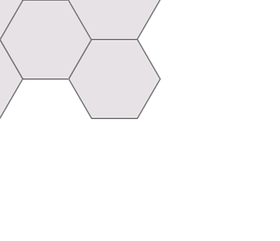
My gap of comprehension is how to algorithmically deduce those x- and y-shifts for arbitrary
prototile compositings from the translation vectors (1, 0) (1/2, sqrt(3)/2) given in Alpha.
sqrt(3)/2 corresponds with the half of the hexagon hight and therefore with the y-shift
(perhaps 1 + 1/2 = 3/2 corresponds to the x-shift) but here ends my insight.


