MODERATOR NOTE: a submission to computations art contest, see more: https://wolfr.am/CompArt-22
Ambiguous rings are composite space curves that can be viewed as either a circle, a polygon, a crown-like shape or an S-like shape, depending on the view direction. In a former community contribution, I discussed the design and 3D printing of a ring that is the cross section of a square and a circular cylinder and can be seen simultanuously as a square or a circle by means of a mirror.
As can be seen from my Wolfram Demonstration "Ambiguous Rings Based on a Polygon"[1], I worked further with these ideas and expanded the "ambiguous rings" design and printing to regular polygons other than squares.
Let us start with the intersection of a pentagonal and a circular cylinder:
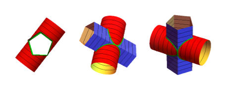
To create a ring or set of rings, we need a closed intersection curve. There needs to be an exact fit of the pentagon inside the longitudinal cross-section of the circular cylinder (two parallel lines).
This requires a radius and axial offset of the circular cylinder adapted to the axial rotation of the pentagonal cylinder. This is done by the two functions fittedRadius and fittedOffset
fittedRadius[\[Theta]0_] := (Cos[
     Mod[(\[Theta]0 + \[Pi]/10), \[Pi]/5]] -
    Cos[Mod[(\[Theta]0 + \[Pi]/10), \[Pi]/5] + 4 \[Pi]/5])/2
fittedOffset[\[Theta]0_] :=
 TriangleWave[{- (3 - Sqrt@5)/8, (3 - Sqrt@5)/8}, 5 \[Theta]0/2/\[Pi]]
If we introduce these functions into the code supplied in [1], we get all the closed intersection curves in function of only one parameter: the axial rotation of the pentagonal cylinder:
polyRingsetCF =
  Compile[{{\[Theta], _Real}, {\[Theta]0, _Real}, {r, _Real}, {\
\[Alpha], _Real}, {n, _Integer}, {d, _Real}},
   Module[{t, s},(*2 part composite curve*)

    t = Sec[2 ArcTan[Cot[n (\[Theta] - \[Theta]0)/2]]/n];
    s = Sec[\[Alpha]] Sqrt[-d^2 + r^2 +
        2 d Cos[\[Pi]/n] t Sin[\[Theta]] -
        Cos[\[Pi]/n]^2 t^2 Sin[\[Theta]]^2];
    {(*part1*){Cos[\[Pi]/n] Cos[\[Theta]] t,
      Cos[\[Pi]/n] t Sin[\[Theta]],
      s - Cos[\[Pi]/n] Cos[\[Theta]] t Tan[\[Alpha]]},
     {(*part 2*)Cos[\[Pi]/n] Cos[\[Theta]] t,
      Cos[\[Pi]/n] t Sin[\[Theta]], -s -
       Cos[\[Pi]/n] Cos[\[Theta]] t Tan[\[Alpha]]}}]];
Manipulate[Module[{r, d},
  rc = fittedRadius[\[Theta]0]; d = fittedOffset[\[Theta]0];
  ParametricPlot3D[
   polyRingsetCF[t, \[Theta]0, rc, 0., 5, d], {t, -\[Pi], \[Pi]},
   PlotStyle -> {{Green, Tube[.04]}}, PlotPoints -> 50,
   PerformanceGoal -> "Quality", SphericalRegion -> True,
   Background -> Lighter[Gray, 0.5],
   ViewAngle -> 4 \[Degree], PlotRange -> 5, Boxed -> False,
   Axes -> False]],
 {{\[Theta]0, -1.,
   Style["axial rotation of polygonal cylinder", Bold, 10]}, -1.5708,
  1.5708, .0001, ImageSize -> Small, Appearance -> "Labeled"}]
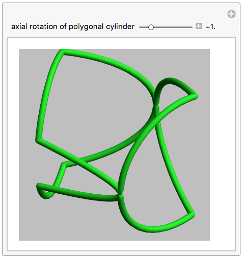
This GIF rotates trough all possible closed ring sets and its corresponding fit of the pentagonal cross section inside the circular.
If we add some inequalities, we can extract a single ring out of this rinset.
polyRingCF =
Compile[{{\[Theta], _Real}, {\[Theta]0, _Real}, {r, _Real}, {\
\[Alpha], _Real}, {n, _Integer}, {d, _Real}, {t1, _Real}, {t2, \
_Real}},(*t1 and t2 are the values of \[Theta] for switching between \
parts*)
Module[{t},(*selection of parts of a composite curve*)
t = Sec[2 ArcTan[Cot[1/2 n (\[Theta] - \[Theta]0)]]/n];
{Cos[\[Pi]/n] Cos[\[Theta]] t,
Cos[\[Pi]/n] Sin[\[Theta]] t,(*select part1 or part 2*)
Piecewise[{{1, \[Theta] <= t1 \[Pi] + 2 \[Theta]0 || \[Theta] >
t2 \[Pi] + 2 \[Theta]0}}, -1]*
Sec[\[Alpha]] Sqrt[-d^2 + r^2 +
2 d Cos[\[Pi]/n] t Sin[\[Theta]] -
Cos[\[Pi]/n]^2 t^2 Sin[\[Theta]]^2] -
Cos[\[Pi]/n] Cos[\[Theta]] t Tan[\[Alpha]]}]];
Module[{d, r, \[Theta]0, t1,
t2}, {d, r, \[Theta]0, t1, t2} = {1/8. (3. - Sqrt[5.]),
1/8. (5. + Sqrt[5.]) + .0001, \[Pi]/10., .3, 1.5};
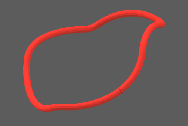
ring5 = ParametricPlot3D[
polyRingCF[\[Theta], \[Theta]0, r, 0., 5, d, t1,
t2], {\[Theta], -0.01, 2 \[Pi]}, PlotStyle -> {{Red, Tube[.04]}},
PerformanceGoal -> "Quality", SphericalRegion -> True,
PlotRange -> 6, Background -> Lighter[Gray, 0.5], ImageSize -> 400,
ViewAngle -> 3.5 \[Degree], Boxed -> False, Axes -> False,
PlotTheme -> "ThickSurface"]]
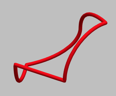
In a GIF while rotating around a vertical (L) or horizontal (R) axis:
We are now ready to print the ring:
Printout3D[ring5, "Sculpteo"]
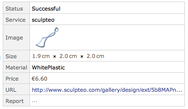
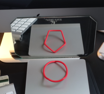
The ring can now be put in front of a mirror and we see a circle shape on the real ring while we observe a pentagon shape reflected in the mirror. This is because, the view line seen from the mirror is at a +/- 90 degree angle from the view line from eye to ring.
Many similar rings are possible. Here are 2 views of a ring resulting from the intersection of a triangular and a circular cylinder:
And finally 2views of a ring from a square- circular cylinder intersection.
All these rings can be printed and will show either circles or polygons depending on the view direction. Using a mirror, one can see both views simultaneously, creating the illusion of "ambiguous rings"!


