Abstract
OpenFOAM stands for Open Field Operation and Manipulation. It is a popular computational fluid dynamics (CFD) software that includes many out-of-the-box solvers to emulate a handful of physics phenomena, such as combustion, compressible flows, incompressible flows and so forth. On the other hand, Wolfram Language is a powerful, multi-paradigm programming language able to create and solve a wide range of tasks. The goal of this project is to construct a connection between the Wolfram Language and OpenFOAM to communicate and to jointly solve CFD problems in both technology stacks.
OpenFOAM workflow
You can divide the process of finding a CFD solution in OpenFOAM into three main steps; preprocessing such as meshing, running the simulation, and analysing the result. Every step comes with its own challenges and all must be completed in order to obtain a good result. The user should keep the actual physics behind the problem in mind and review the results after each step.
Preprocessing
Preprocessing is the first step to solve a CFD problem. You are required to identify the physical laws of your problem and you need to construct a mesh. OpenFOAM needs one the two files called dictionaries to generate a mesh: blockMesh or snappyHexMesh. The first one has a mathematical approach and defines the scenario of your problem in geometric terms ensuring consistency. The latter requires a Computational Aided Design (CAD) software to construct. To gain deeper understanding in these dictionaries, please refer to the official OpenFOAM documentation.
Running Simulation
Once the mesh is created and the appropriate boundaries are set up, the user can define the solver and run the simulation. This is done by solving the partial differential equations that govern the phenomena with numerical methods. Thus, many criteria start to rise such as discretization method, convergence criteria, solution method and so forth. For instance, in fluid phenomena these are some of the governing equation the simulation tries to solves by setting up some conditions upfront:
$$ \rho_{,t} + (\rho v_{i})_{,i}=0 \, \, \, \, \, \, \, Mass$$ $$ \rho ( u_{k,t} + u_{i} u_{k,i})= p_{,k} + T_{,k}+ f_{k} \, \, \, \, \, \, \, Navier-Stokes$$
Depending on the problem at hand, more variables and equations may come into play, such as internal energy for example.
Postprocessing
After obtaining a solution, the user needs to evaluate the results, check its consistency, and compare it with experimental findings. The postprocessing stage is usually handled by dedicated software like Paraview and GNU Plot. The user can also collect the data and display it using some programming language like Wolfram Language.
Mathematica Mesh
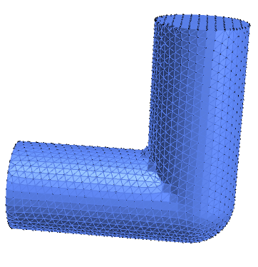
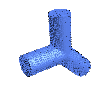
Mathematica/Wolfram Language (WL) provides tools to create and display all sorts of interesting meshes, see Element Mesh Visualization and Discretize Region. The meshes generated inside WL are predominantly made of tetrahedral elements. The reader can try to generate the following meshes:
Pipe mesh
DiscretizeRegion[ RegionUnion[ Region[Cylinder[{{0, 0, 0}, {1, 0, 0}}, 0.25]], Region[Ball[{1, 0, 0}, 0.25]], Region[Cylinder[{{1, 0, 0}, {1, 0, 1}}, 0.25]] ], Method -> "DualMarchingCubes" ]
Pipes joint
DiscretizeRegion[
 RegionUnion[
  Region[Cylinder[{{0, 0, 0}, {1, 0, 0}}, 0.25]],
  Region[Ball[{1, 0, 0}, 0.25]],
  Region[Cylinder[{{1, 0, 0}, {1, 0, 1}}, 0.25]],
  Region[Cylinder[{{1, 0, 0}, {1 + Sqrt[1/2], 0, -Sqrt[1/2]}}, 0.25]]
  ],
 Method -> "DualMarchingCubes"
 ]
OpenFOAM Mesh
Depending on the geometry, it is fairly easy to generate a mesh inside Mathematica and to repair it if necessary. On the other hand, OpenFOAM generates hexahedral meshes from dictionary blockMesh files. In order to establish a connection between Mathematica and OpenFOAM a tetrahedral element mesh need to be converted into a hexahedral mesh.
A hexahedral mesh of a 2D airfoil
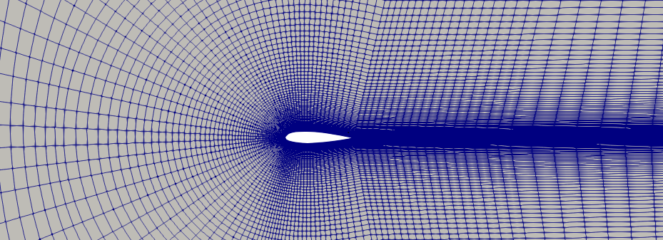
To see more neat examples, please refer to the tutorials inside OpenFOAM repository.
Preprocessing stage link between Mathematica and OpenFOAM
1. Mesh Generation in Mathematica
The first step to solve the problem is to actually be able to generate any type of Mesh inside Mathematica and specify boundaries and internal faces, thus some utility functions are defined as follows:
(*Utility Functions*)

Clear[PermuteToMinLast, EncodeOpenFOAM,
  FindIndexMapping];  (*Clear values for PermutetoMinLast, EncodeOpenFOAM, \
FinIndexMappin*)

PermuteToMinLast[indices : {__Integer}] :=
 RotateLeft[indices,
  First@Ordering[indices,
    1]]    (*Permutate to put  the minimum value at the end*)

EncodeOpenFOAM[indices : {__?NumberQ}] :=
 "(" <> StringJoin@Riffle[Map[ToString[#, FortranForm] &, indices - 1], " "] <>
   ")" (*Encodes the lists values  into a readable OpenFOAM format*)

EncodeOpenFOAM[Tetrahedron[indices : {__Integer}]] :=
 EncodeOpenFOAM@Part[indices, {2, 1, 3, 3, 4, 4, 4, 4}] (*Enconding format*)

EncodeOpenFOAM[Polygon[indices : {__Integer}]] :=
 EncodeOpenFOAM@Part[indices, {2, 1, 3, 3}]  (*Enconding format*)

FindIndexMapping[set1_List, set2_List] :=
 Dispatch@Thread[
   Range[Length[set2]] ->
    Flatten@Map[elem \[Function] FirstPosition[set1, elem], set2]]

TetrahedralBoundary[Tetrahedron[{p2_, p1_, p3_, p4_}]] :=
 {Polygon[Sort@{p3, p2, p1}] -> {p2, p1, p3, p3},
  Polygon[Sort@{p2, p3, p4}] -> {p2, p3, p4, p4},
  Polygon[Sort@{p3, p1, p4}] -> {p3, p1, p4, p4},
  Polygon[Sort@{p1, p2, p4}] -> {p1, p2, p4, p4}}
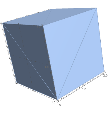
Once the utility functions are defined, a region is given as follows:
\[CapitalOmega] =
 DiscretizeRegion[Region[Cuboid[{1, 1, 1}]], MaxCellMeasure -> 1]
This particular case is just a simple cuboid with tetrahedral mesh elements.
2. Encoding Tetrahedral Elements as Hexahedral Elements in OpenFOAM
The tetrahedral elements from the Wolfram Language need to be encoded in OpenFOAM. This is achieved by contracting the vertices of a hexahedron as follows:
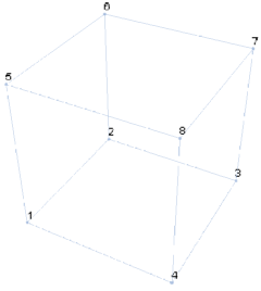
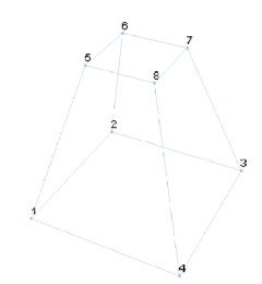
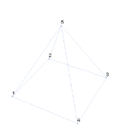
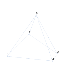
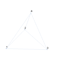
For starters, the typical cell in BlockMesh dictionary is a hexahedron. Thus, in order to mimic a tetrahedron, one face ( 8 7 6 5 ) is collapsed into a single vertex. In a second step, the face (4 1 2 3 ) is contracted into a single edge. Please note that the vertex enumeration changes and it is important to keep each vertex "history" in mind since the faces of boundary conditions are later specified using the same vertices.
3. Recognizing the Boundary Conditions
Once the domain is generated and the utility functions have been defined, the points of the domain are generated.
(*Points*)

pts = MeshCoordinates[\[CapitalOmega]]  ;(*Generates the  data points of the \
mesh*)

pointString =
  "vertices\n(\n  " <> StringJoin@Riffle[Map[EncodeOpenFOAM, pts], "\n  "] <>
   "\n);\n"; (* Encodes the data points in a functional OpenFOAM format*)
With the mesh generated the building blocks of the mesh can be encoded into an OpenFOAM friendly format as follows:
\[CapitalOmega]Cells =
  Map[PermuteToMinLast,
   MeshCells[\[CapitalOmega],
    3], {2}] ; (*Permutes the tetrahedron  in order to set the minimum index \
to be last in the list , thus collapsing the hexaedron in that index.*)

tets = Map[
   EncodeOpenFOAM, \[CapitalOmega]Cells]; (*Encodes previous result into a \
OpenFOAM readable format*)

blockString =
  "blocks\n(\n hex " <>
   StringJoin@Riffle[tets, " (1 1 1) simpleGrading (1 1 1)\n hex "] <>
   " (1 1 1) simpleGrading (1 1 1)\n);\n"; (*Writes the string that generates \
the hex blocks into OpenFOAM *)
So far the cuboid mesh generated has been encoded into a friendly OpenFOAM format by collapsing the vertices. The remaining problem is that a mesh without any boundary conditions is not useful since solving PDEs, in general, requires boundary specifications.
In order to identify the faces of tetrahedron, the utility functions defined above are used as follows:
(*Faces*)

Flatten@Map[
   TetrahedralBoundary, \[CapitalOmega]Cells] ;(* Flatten out lists and and \
repeats the last value *)


faceRules = Flatten@Map[TetrahedralBoundary, \[CapitalOmega]Cells];
4. Boundary Definition
The typical boundary components of a mesh required in fluid dynamics are inlet, wall, and outlet. These boundary types are defined based on tetrahedral faces. Keep in mind that is not enough to be able to recognize theses face in Mathematica. They also need to be encode according to blockMesh dictionary conventions.
(*Boundary and Internal Components *)

 \[Delta]\[CapitalOmega] = RegionBoundary[\[CapitalOmega]]; (* Region Boundary*)

 \[Delta]Mesh = MeshCells[\[Delta]\[CapitalOmega], 2]; (* Shows polygons *)

 \[Delta]Pts =
  MeshCoordinates[\[Delta]\[CapitalOmega]]; (*Mesh coordinates of the \
Boundary *)

iPts = Complement[pts, \[Delta]Pts];

I \[Delta]indexRules = FindIndexMapping[pts, \[Delta]Pts]
iIndexRules = FindIndexMapping[pts, iPts];
For the inlet and outlet, we collect all tetrahedral faces that satisfy some given constraints. In our particular case of a cuboid it is $x = 1$ for the flow entrance and $x = 2$ for the flow exit. The definition of the boundary will change depending on the domain scenario, therefore the user is responsible to properly define inlet and outlet conditions.
(*Inlet*)

inletCondition := (x == 1)

inlet\[Delta]Indices =
  Flatten@Position[
    Apply[{x, y, z} \[Function] Evaluate[inletCondition],
     Round[\[Delta]Pts, 10^-12], {1}], True];

inletCells =
  Replace[Select[\[Delta]Mesh,
    SubsetQ[inlet\[Delta]Indices, First[#]] &], \[Delta]indexRules];


faces = Map[EncodeOpenFOAM,
   Replace[Map[Sort, inletCells, {2}], faceRules, 1]];

inletString =
  "inlet\n{\n  type patch;\n  faces\n  (\n    " <>
   StringJoin@Riffle[faces, "\n    "] <> "\n  );\n}\n";(*faces encoded to OpenFOAM*)
And for the outlet:
(* Outlet*)

 outletCondition := (x == 2)

outlet\[Delta]Indices =
 Flatten@Position[
   Apply[{x, y, z} \[Function] Evaluate[outletCondition],
    Round[\[Delta]Pts, 10^-12], {1}], True]


 outletCells =
  Replace[Select[\[Delta]Mesh,
    SubsetQ[outlet\[Delta]Indices, First[#]] &], \[Delta]indexRules];

faces = Map[EncodeOpenFOAM,
   Replace[Map[Sort, outletCells, {2}], faceRules, 1]];
 outletString =
  "outlet\n{\n  type patch;\n  faces\n  (\n    " <>
   StringJoin@Riffle[faces, "\n    "] <> "\n  );\n}\n";  (*faces encoded to OpenFOAM*)
Finally the wall, the remaining boundary, is obtained as follows:
(*Wall*)

wallCells =
  Complement[Replace[\[Delta]Mesh, \[Delta]IndexRules, {3}],
   Join[inletCells, outletCells]];


faces = Map[EncodeOpenFOAM, Replace[Map[Sort, wallCells, {2}], faceRules, 1]];

wallString =
  "wall\n{\n  type wall;\n  faces\n  (\n    " <>
   StringJoin@Riffle[faces, "\n    "] <> "\n  );\n}\n"; (* Encodes faces into the OpenFOAM dictionary*)
The boundary conditions can be visualized with the following code:
wallMesh = MeshRegion[pts, wallCells]
outletMesh = MeshRegion[pts, outletCells]
inletMesh= MeshRegion[pts, inletCells]
Which results into the boundary shapes:
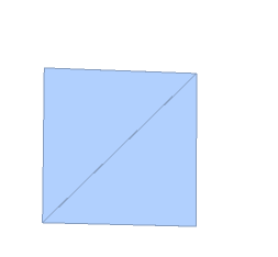

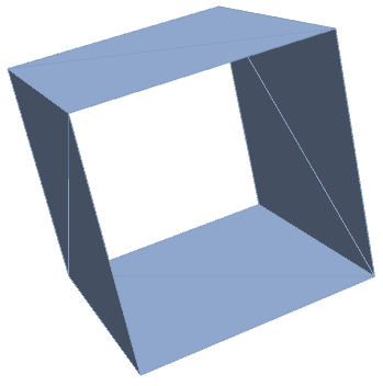
Changing the mesh region to a cylinder, the algorithm gives good results recognizing the boundaries.
\[CapitalOmega] =
 DiscretizeRegion[
  Region[Cylinder[{{0, 1/2, 1/2}, {1, 1/2, 1/2}}, 1/4]],
  MaxCellMeasure -> 1]
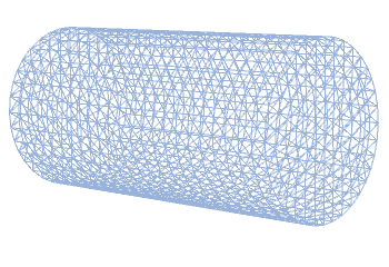
Even though the cylindrical mesh is easily generated inside Mathematica and the boundary conditions are easily specified, the resulting mesh specification in OpenFOAM does not compile and fails. Hence, for the moment, we are limited to the cuboid, which works perfectly and passes OpenFOAM's checkMesh check.
Conclusion and future work
- Build a more robust algorithm to encode the boundary conditions into OpenFOAM.
- Explore the connections between snappyHexMesh and Mathematica
- Explore the connectivity options with OpenFOAM
References
[1] OpenFOAM documentation
 Attachments: