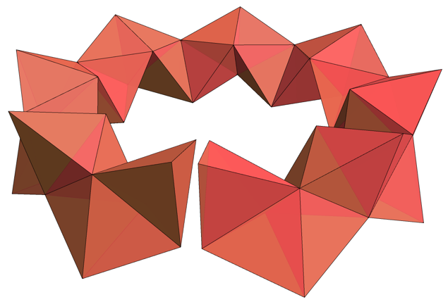
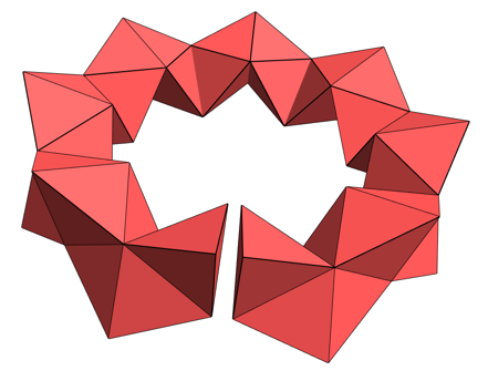
Posting detailed code here. The initial image, with the gap: I zeroed out the "bestVec", which was used in an earlier attempt to optimize
faces = {{2, 3, 4}, Reverse@ {1, 3, 4}, {1, 2, 4}, {1, 2, 3}};
faces = {{2, 3, 4}, Reverse@ {1, 3, 4}, {1, 2, 4},
Reverse@{1, 2, 3}}; (* important *)
facesRev = Reverse /@ faces;
startV = N@{{0, 0,
Sqrt[2/3] - 1/(2 Sqrt[6])}, {-(1/(2 Sqrt[3])), -(1/2), -(1/(
2 Sqrt[6]))}, {-(1/(2 Sqrt[3])), 1/2, -(1/(2 Sqrt[6]))}, {1/
Sqrt[3], 0, -(1/(2 Sqrt[6]))}};
bestVec =
0 Flatten[{{0.0030786234640517588`, -0.0012713757639448969`,
0.005921062251657448`}, {-0.0017401845032882991`, \
-0.0020681936130036126`,
0.005393869601475211`}, {0.0020298099367479444`,
0.0005102453293635576`,
0.0029724999287053682`}, {-0.00023558451188598613`,
0.0009452979460132543`,
0.005798188590794252`}, {-0.000027554327839240944`,
0.0020459864295050674`,
0.0034435421203985097`}, {0.0025981484730485446`,
0.0007355749150532`,
0.0012539109619916077`}, {-0.006626782180945919`, \
-0.0005807683214184328`, 0.0038058021075369495`}}];
choices = {1, 2, 3, 3, 2, 1, 1, 2, 3, 3, 2, 1, 1, 2, 3, 3, 2, 1, 1, 2,
3, 3, 2, 1, 1, 2, 3, 3, 2, 1, 1, 2, 3, 3, 2, 1, 1, 2, 3, 3, 2, 1,
1, 2, 3, 3, 2,
1}; (* found by luck and trial and error in August 2013 *)
perms = Permutations[Range[4]];
dist[tet1_, tet2_] :=
Min[Table[Max[Norm /@ ((tet1 - tet2[[pp]]))], {pp, perms}]];
nextTetPushed[currentV_, freeVert_, moveVertInd_, pVec_] := (
vertToMove = DeleteCases[Range[4], freeVert][[moveVertInd]];
vertToMovVal = currentV[[vertToMove]];
reflectface = DeleteCases[Range[4], vertToMove];
centroid = Mean[currentV[[reflectface]]];
newpos = vertToMovVal + 2 (centroid - vertToMovVal);
newVerts = ReplacePart[currentV, vertToMove -> newpos];
{# + pVec & /@ newVerts, vertToMove})
count = 0; Clear[func, st];
func[{a1_?NumericQ, a2_, a3_, a4_, a5_, a6_, a7_, a8_, a9_, a10_,
a11_, a12_, a13_, a14_, a15_, a16_, a17_, a18_, a19_, a20_,
a21_}] := (st[0] = {startV, 1};
change =
Flatten[Table[{{a1, a2, a3}, {a4, a5, a6}, {a7, a8, a9}, {a10,
a11, a12}, {a13, a14, a15}, {a16, a17, a18}, {a19, a20,
a21}}, {10}], 1];
Do[st[i] =
nextTetPushed[st[i - 1][[1]], st[i - 1][[2]], choices[[i]],
change[[i]]], {i, Length[choices]}];
L = Length[choices];
data = st /@ Range[0, L];
store = {{a1, a2, a3}, {a4, a5, a6}, {a7, a8, a9}, {a10, a11,
a12}, {a13, a14, a15}, {a16, a17, a18}, {a19, a20, a21}};
bb = dist[data[[1, 1]], data[[-1, 1]]]; count++;
If[Mod[count, 500] == 0, Print[{bb, Norm[Flatten[store]]}]]; bb);
funcPercent[{a1_?NumericQ, a2_, a3_, a4_, a5_, a6_, a7_, a8_, a9_,
a10_, a11_, a12_, a13_, a14_, a15_, a16_, a17_, a18_, a19_, a20_,
a21_}] := (st[0] = {startV, 1};
change =
Flatten[Table[{{a1, a2, a3}, {a4, a5, a6}, {a7, a8, a9}, {a10,
a11, a12}, {a13, a14, a15}, {a16, a17, a18}, {a19, a20,
a21}}, {10}], 1];
Do[st[i] =
nextTetPushed[st[i - 1][[1]], st[i - 1][[2]], choices[[i]],
change[[i]]], {i, Length[choices]}];
L = Length[choices];
data = st /@ Range[0, L];
store = {{a1, a2, a3}, {a4, a5, a6}, {a7, a8, a9}, {a10, a11,
a12}, {a13, a14, a15}, {a16, a17, a18}, {a19, a20, a21}};
bb = dist[data[[1, 1]], data[[-1, 1]]]; count++;
dataAll = Flatten[First /@ data, 1];
dubs =
Table[ Count[dataAll,
p_ /; Norm[p - dataAll[[i]]] < .35 /1000] , {i,
Length[dataAll]}];
dups = dataAll[[Position[dubs, 2] // Flatten]];
close[p_] := Select[dataAll, Norm[# - p] < .35 /1000 &];
close[p_] := False;
dataClose = close /@ dataAll;
dataAllFixed = Table[ Mean[dataClose[[i]]], {i, Length[dataAll]}];
dataTetFixed = Partition[dataAllFixed, 4];
ans = {Max[#], Min[#]} & @
Flatten[Table[
Norm[#[[1]] - #[[2]]] & /@ Subsets[dataTetFixed[[i]], {2}], {i,
48}]];
ans = ans[[1]] - ans[[2]];
If[ans < best, best = ans; storedBest = store];
If[Mod[count, 200] == 0,
Print[{count, ans, bb, Norm[Flatten[store]], best}]]; ans + 10 bb);
funcPercent[Flatten[bestVec]]; (* important *)
dataAll = First /@ data;
aa = {Max[#], Min[#]} & @
Flatten[Table[
Norm[#[[1]] - #[[2]]] & /@ Subsets[dataAll[[i]], {2}], {i,
48}]];
aa[[1]] - aa[[2]];
dataPols = First /@ data;
{vp, vv} = {{-0.5736193192422712`, -1.2442823717517009`,
0.40843880317618597`}, {-0.6180067894290332`,
0.8698216744526492`, -0.3761742628418529`}};
cols = Lighter /@
Prepend[Join @@ Table[{Blue, Green, Green, Blue, Red, Red}, {50}],
Red];
gg = Graphics3D[
Table[{ EdgeForm[Black], FaceForm[{Opacity[.9], cols[[i]]}],
FaceForm[Lighter@Red, Green],
Polygon[(dataPols)[[i]][[#]]] & /@
If[EvenQ[i], facesRev, faces]}, {i, Length@data - 1}],
BoxRatios -> Automatic, ViewAngle -> .47 2, ViewPoint -> vp,
ViewVertical -> vv, PlotRegion -> {{-.15, 1.15}, {-.25, 1.45}},
PlotRange -> {All, {{-1, 1}, {-1, 1}, {-1, 1}}}[[1]],
Boxed -> False, Axes -> ! True, ImageSize -> 700,
Lighting -> {Automatic, "Neutral"}[[2]]]

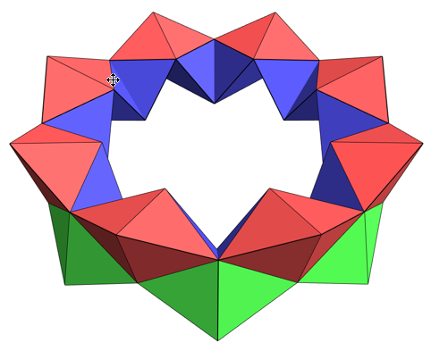
There are some orientation issues.... but they were fixed above. Inside is green. Outside is red. So orientation is all good. Next it makes sense to remove the interior faces.
polys = Cases[gg, Polygon[_], \[Infinity]];
Length[polys];
polys1 = polys /. Polygon[z_] :> Polygon[Sort[z]];
Last /@ (tt = Tally[polys]);
(polys1 = First /@ Select[tt, #[[2]] >= 1 &]) // Length
g1 = Graphics3D[{Opacity[1], FaceForm[Lighter@Red, Green],
Table[Polygon[polys1[[i, 1]]], {i, Length[polys1]}]},
Boxed -> False, Axes -> ! True, AxesLabel -> {x, y, z},
ImageSize -> 600, Lighting -> "Neutral"]
polys = Cases[g1, Polygon[_], \[Infinity]];

Moving the error around to make the last = first. Joint work with Michael Elgersma.This defines the rim edges.
special[{L1_, L2_}] := ((( L1[[1]] < .4 - .3 L1[[ 2]]) &&
( L2[[1]] < .4 - .3 L2[[ 2]])) ||
(((
L1[[1]] > .4 - .3 L1[[ 2]]) &&
( L2[[1]] > .4 - .3 L2[[ 2]])))) && (Norm[
L1[[{2, 3}]] - cen[[{2, 3}]]] > 1.7 &&
Norm[L2[[{2, 3}]] - cen[[{2, 3}]]] > 1.7 ) ;
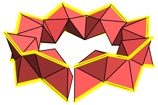
This shows the rim edges in yellow. Sort of like railway tracks.
cen = {.7, 2, 0};
qq = Flatten[
Cases[g1,
Polygon[z_] :> {Line[{z[[1]], z[[2]]}], Line[{z[[2]], z[[3]]}],
Line[{z[[3]], z[[1]]}]}, \[Infinity]], 1];
Show[g1, Graphics3D[{Thickness[.04],
Table[{www =
Which[special@q, Directive[{Yellow, Thickness[.02]}] ,
special@q, Directive[{Yellow, Thickness[.02]}] ,
True, Directive[{Black, Thickness[.004]}]],
Line@q}, {q, First /@ qq}]}](*, plane;*) ,
PlotRange -> {{-2.2, 2.2}, {-1, 5}, {-2.5, 2.5} 1.1},
ImageSize -> 500, Boxed -> False, Axes -> False]

Now the idea is to start the process from the beginning with a parameter, \, that is used to length the rim edges, while all the other edges remain at length 1. This is a little trickier than I thought. I use SOLVE at each point. Here we change the start to allow \ for the one rim edge.
startVerts[\[Epsilon]_] := {startV [[1]], {x, y, z} /. Quiet@Solve[{
({x, y, z} - startV[[1]]).({x, y, z} - startV[[1]]) == (
1 + \[Epsilon])^2,
({x, y, z} - startV[[3]]).({x, y, z} - startV[[3]]) == 1,
({x, y, z} - startV[[4]]).({x, y, z} - startV[[4]]) ==
1}, {x, y, z}][[1]], startV[[3]], startV[[4]]};
startVerts[.01 0]
Out[] = {{0., 0., 0.612372}, {-0.288675, -0.5, -0.204124}, {-0.288675, 0.5, -0.204124}, {0.57735, 0., -0.204124}}
nextTetElgersma[currentV_, freeVert_, moveVertInd_, \[Epsilon]_] := (
vertToMove = DeleteCases[Range[4], freeVert][[moveVertInd]];
vertToMovVal = currentV[[vertToMove]];
reflectface = DeleteCases[Range[4], vertToMove];
centroid = Mean[currentV[[reflectface]]];
newpos = vertToMovVal + 2 (centroid - vertToMovVal);
oldVerts = Delete[currentV, vertToMove];
edges = {#, newpos} & /@ oldVerts;
pos = Position[edges, _?special];
newVerts = ReplacePart[currentV, vertToMove ->
If[pos == {},
Select[{x, y, z} /. Quiet@Solve[{
({x, y, z} - edges[[1, 1]]).({x, y, z} -
edges[[1, 1]]) == 1,
({x, y, z} - edges[[2, 1]]).({x, y, z} -
edges[[2, 1]]) == 1,
({x, y, z} - edges[[3, 1]]).({x, y, z} -
edges[[3, 1]]) == 1}, {x, y, z}],
Norm[# - vertToMovVal] > .5 &][[1]],
ss = edges[[pos[[1, 1]]]];
others = Complement[Range[3], {pos[[1, 1]]}]; specCount++;
Select[{x, y, z} /. Quiet@Solve[{
({x, y, z} - ss[[1]]).({x, y, z} - ss[[1]]) == (
1 + \[Epsilon])^2,
({x, y, z} - edges[[others[[1]], 1]]).({x, y, z} -
edges[[others[[1]], 1]]) == 1,
({x, y, z} - edges[[others[[2]], 1]]).({x, y, z} -
edges[[others[[2]], 1]]) == 1}, {x, y, z}],
Norm[# - vertToMovVal] > .5 &][[1]] ]];
{newVerts, vertToMove});
The following was found using FindMinimum and also some trial and error at the start. The value of 0.0027 means that each edge is between 1. and 1.0027 in length. So the error in terms of difference from a regular tetrahedron of side length 1.00137 is about 0.13%, or 1/7 of one percent. This is likely within the tolerances of a 3D printing machine. Still, it would be nice to make it even smaller.
bestepsilonvalue = 0.002743438209350663;
The last tetrahedron is now indistinguishable from the first.
funcElgersma[.002743438209350663]
Out[] = 2.06186*10^-14
We fix the last points to match exactly, though at 10^-14 difference this hardly matters.
data[[-2]]
data[[1]]
data[[-2]] = {{data[[-2, 1, 1]], data[[1, 1, 2]], data[[1, 1, 3]], data[[1, 1, 4]]}, data[[1, 2]]}
Here is a picture of the fake tetrahedral torus.
gg = Graphics3D[
Table[{ EdgeForm[Black],
FaceForm[{Opacity[1], GrayLevel[RandomReal[{.3, .9}]];
cols[[i]]}], Polygon[(First /@ data)[[i]][[#]]] & /@ faces}, {i,
Length@data - 1}], BoxRatios -> Automatic, ViewAngle -> .47 2,
ViewPoint -> vp, ViewVertical -> vv,
PlotRegion -> {{-.15, 1.15}, {-.25, 1.45}},
PlotRange -> {All, {{-1, 1}, {-1, 1}, {-1, 1}}}[[1]],
Boxed -> False, Axes -> ! True, ImageSize -> 500,
Lighting -> {Automatic, "Neutral"}[[2]]]
