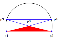
Suppose the lamina is not exactly half disk. We can compute this extended problem easily with Mathematica.

Particulary, we are looking for the line P3_P4 that cuts the lamina into two pieces of same area. So the area above p3_p4 is basically that the area of Disk P3_P0_P4 minus the area of the blue triangle. The entire area of the lamina is that the area of Disk P0_P1_P3_P4_P2 plus the area of the red triangle. Call the obtuse angle of the red triangle: "phi"; the obtuse angle of the blue triangle : "theta", we have
r=Sqrt[(1/2)^2+y0^2];
\[Phi]=2*ArcTan[1/(2*y0)];
s=(2\[Pi]-\[Phi])/2*r^2+1/2*r^2*Sin[\[Phi]];
res={r,\[Phi],\[Theta]/.FindRoot[r^2/2*\[Theta]-Sin[\[Theta]]/2*r^2==s/2,{\[Theta],\[Pi]/2}]}
where r is radius of the lamina, P0 = {0,y0} the center and the coordinate of p1 and p2 be {+/- 1/2 ,0} respectively . The above code is all you need to resolve this problem.
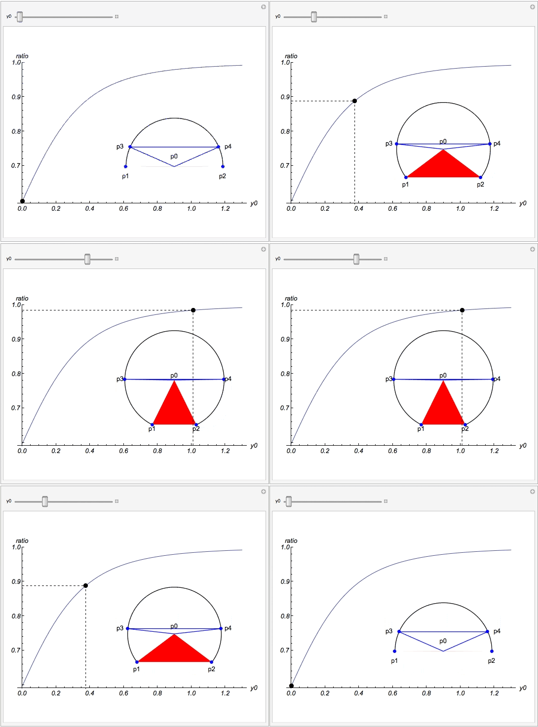
I can merge the result and some extra graphics code to make a dynamic presentation:

where y0 is the distance between P0 and chord P1_P2 and the ratio in the vertical axis is defined as 1 minus (height of blue triangle divides the radius of the circle). Certainly , when the center moves very far this ratio should be one, which means the diameter cuts the laminar into two identical parts approximately.
Copyable code:
Manipulate[
{r, \[Phi], \[Theta]} = f[y0];
p0 = {0, y0};
p1 = {-1/2, 0};
p2 = {1/2, 0};
p3 = {-r*Sin[\[Theta]/2], y0 + r*Cos[\[Theta]/2]};
p4 = {r*Sin[\[Theta]/2], y0 + r*Cos[\[Theta]/2]};
tracker = {y0, 1 - Cos[f[y0][[3]]/2]};
g = Graphics[
{
Circle[{0, y0},
r, {-((\[Pi] - \[Phi])/2), (3*\[Pi] - \[Phi])/2}],
{Red, Polygon[{p1, p2, {0, y0}}]},
{Blue, PointSize[0.03], Point[{p1, p2}]},
{Blue, PointSize[0.03], Point[{p3, p4}]},
{Blue, Line[{p0, p3, p4, p0}]},
Text["p0", p0 + {0, 0.1}],
Text["p1", p1 - {0, 0.1}],
Text["p2", p2 - {0, 0.1}],
Text["p3", p3 - {0.1, 0}],
Text["p4", p4 + {0.1, 0}]
}];
Plot[1 - Cos[f[x][[3]]/2], {x, 0.001, 1.3},
PlotRange -> Full,
AxesLabel -> {"y0", "ratio"}, LabelStyle -> Directive[13, Italic],
Epilog -> {
Inset[Style[g, Magnification -> 1.3], {0.9, 0.75 + y0/35}],
{PointSize[0.02], Point[tracker]},
{Dashed, Line[{{0, tracker[[2]]}, tracker, {tracker[[1]], 0}}]}
}, ImageSize -> {500, 400}
]
, {y0, 0.001, 1.3}, Initialization :> (
f[y0_] := Module[{r, \[Phi], s, res},
r = Sqrt[(1/2)^2 + y0^2];
\[Phi] = 2*ArcTan[1/(2*y0)];
s = (2 \[Pi] - \[Phi])/2*r^2 + 1/2*r^2*Sin[\[Phi]];
res = {r, \[Phi], \[Theta] /.
FindRoot[
r^2/2*\[Theta] - Sin[\[Theta]]/2*r^2 == s/
2, {\[Theta], \[Pi]/2}]}
])]