Wanted to share with my kids the classical experiment on a rolling object down an incline plane using legos, arduino and Mathematica for the Raspberry Pi.
Using a window valance and some lego technic pieces we proceeded to build the inclined plane platform.
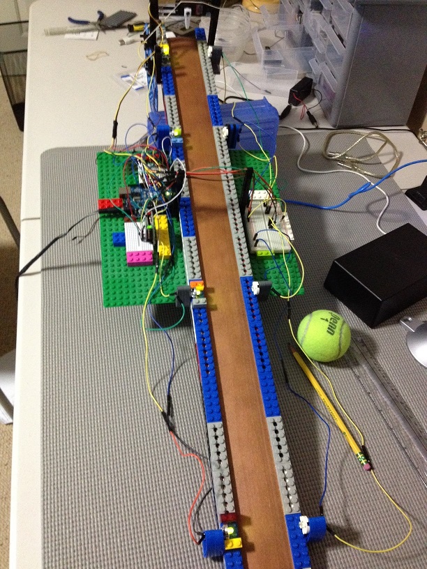
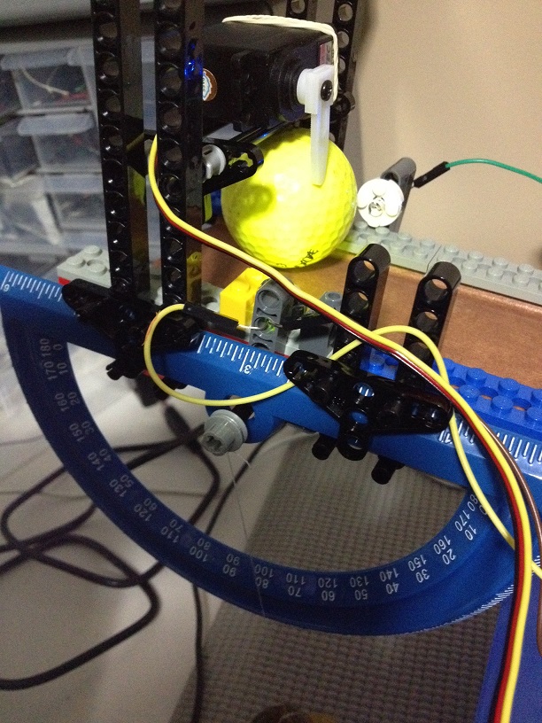
Using legos was great to allow to attach both leds and photorresistors to the inclined plane. It also allowed us to set up build a platform from where to attach a servo motor and a protractor to measure the angle of inclination.
We'll detect when the ball reaches a certain point of the platform by the the disminution of the LED light received at the photoresistors.
.JPG&userId=78214)
The adafruit web site is a very good site to explain the details on how to connect the photoresistors and leds to the Arduino.
http://learn.adafruit.com/adafruit-arduino-lesson-2-leds/ledshttp://learn.adafruit.com/photocells/using-a-photocellAs the readings of the photocells require of analog inputs, we decided to use a spare arduino we had at our disposal, and to have more fun, use XBEE modules to connect the arduino to the raspberry pi.
.JPG&userId=78214)
The following is the code at the Arduino.
#include <Servo.h>
int servoPin = 9;
int LightSensor[4]={A1,A2,A3,A4};
int current[4]={0,0,0,0};
double timers[4]={0,0,0,0};
int previous[4]={0,0,0,0};
Servo servo;
int i=0;
double factor=0.7;
double timer = 0;
int inByte =0;
void setup()
{
Serial.begin(19200);
servo.attach(servoPin);
servo.write(0);
delay(2000);
for (i=0;i<4;i++){
previous[i]=analogRead(LightSensor[i]);
}
}
void loop()
{
if(Serial.available()>0){
inByte=Serial.read();
if (inByte==65) {
servo.write(90);
timer=millis();
trackBall();
for (i=0;i<4;i++){
Serial.println(timers[i]);
}
servo.write(0);
}
}
}
void trackBall(){
int m =0;
while (m<4){
current[m]=analogRead(LightSensor[m]);
if (current[m]<factor*previous[m]){
timers[m]=millis()-timer;
m++;
}
}
}
Mathematica code and results to follow
serial = DeviceOpen["Serial", {"/dev/ttyUSB0", "BaudRate" -> 19200}]
lengths = {0., 0.175, 0.43,
0.69} ;(*Distance between light sensors in meters*)
data = {};(*List to capture the time between sensors*)
ping := Module[{}, DeviceWriteBuffer[serial, {"A"}]; Pause[3];
ToExpression[StringSplit[FromCharacterCode[DeviceReadBuffer[serial]]]]/1000]
(*Function pings sends an "A" to the arduino to release the ball and \
collect timing*)
Button["Collect Data", data = Append[data, ping]]
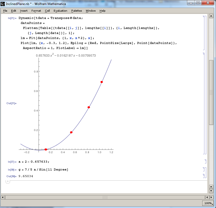
Dynamic[tdata = Transpose@data;
dataPoints =
Flatten[Table[{tdata[[i, j]], lengths[[i]]}, {i,
Length[lengths]}, {j, Length[data]}], 1];
lm = Fit[dataPoints, {1, x, x^2}, x];
Plot[lm, {x, -0.3, 1.2},
Epilog -> {Red, PointSize[Large], Point[dataPoints]},
AspectRatio -> 1, PlotLabel -> lm]]
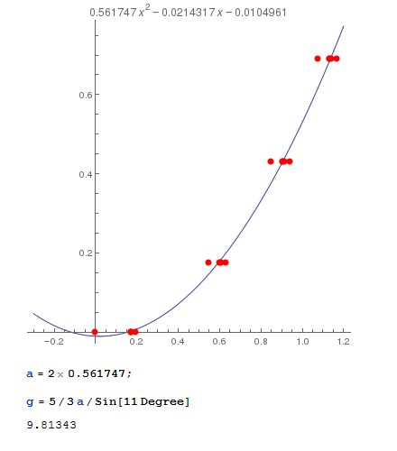
Using a hollow ball, we can work out the gravity value
Using a golf ball
A couple of videos of the experiment in action
https://www.youtube.com/watch?v=4eRZ48N3vM8https://www.youtube.com/watch?v=eLVPpEcyw_0https://www.youtube.com/watch?v=53WaEcRWY_0


