The above GIF of a cube skeleton demonstrates the principle of "Perspective Anamorphism": you need a particular viewpoint to see the picture undeformed. All other viewpoints give a deformed picture. In the paper "Anamorphosis: optical games with perspective's playful parent" by António Araújo, the following example set me to work and see how this could be achieved using Mathematica.
We first write a function that maps an image point I as an perspective point Q. The view line is the HalfLine between the eye at E and the image point at I. Q is the intersection between the view line and either the cylinder or the xy plane.
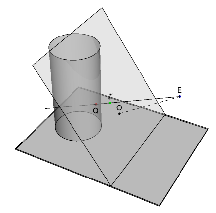
This function finds both intersections of the view line and selects the applicable one. xv sets the location of the eye and phi is the view direction or the angle between the the view line and the xy plane.
anaPoint3D[iPt : {xi_, yi_, zi_}, phi_, xv_] :=
 Module[{eye, ray, solCyl, solFlr},
  eye = {xv, 0, xv Tan[phi]}; ray = HalfLine[{eye, iPt}];
  solCyl = NSolve[{{x, y, z} \[Element] ray,
     Norm[{x, y}] == 1 && z > 0}, {x, y, z}];
  solFlr = NSolve[{{x, y, z} \[Element] ray, z == 0}, {x, y, z}];
  First[If[solCyl == {}, {x, y, z} /. solFlr,
    Nearest[{x, y, z} /. solCyl, eye]]]]
The next GIF shows the function in action, following a point on a circle and its perspective map divided between the cylinder and the xy plane:
We are now ready to try this on a cube skeleton using PolyhedronData. The vertices of the cube do not give enough information about the edges for our purpose. The map of the edges, when mapped onto the cylinder, will not be a straight line but a curve. We therefore need more points i.e. a function that will interpolate a number of points between two vertices.
interpol3D[{pt1 : {x1_, y1_, z1_}, pt2 : {x2_, y2_, z2_}}, n_ : 100] :=
  Table[(1 - t) pt1 + t pt2, {t, 0, 1, 1/n}]
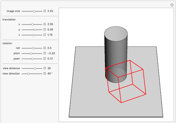
This Manipulate lets one size, translate or rotate the cube and evaluate different eye locations and view directions:
Manipulate[Module[{cubeGC, edgeIndexes, ptsI, ptsQ, ptsQsplit},
  cubeGC = PolyhedronData["Cube", "GraphicsComplex"];
  edgeIndexes = PolyhedronData["Cube", "EdgeIndices"];
  ptsI = \[Rho] ParallelMap[{x, y, z} +
       RollPitchYawMatrix[{\[Alpha], \[Beta], \[Gamma]}].#1 &, \
(interpol3D[#1, 50] &) /@ (cubeGC[[1]][[#1]] &) /@ edgeIndexes, {2}];
  ptsQ = Map[anaPoint3D[#1, \[Phi], xv] &, ptsI, {2}];
  ptsQsplit = (SplitBy[#1, Last[#1] == 0. &] &) /@ ptsQ;
  Graphics3D[{{White,
     Cuboid[{-4, -4, -.1}, {5, 4, 0}]}, {Opacity[.85],
     Lighter[Gray, .95],
     Cylinder[{{0, 0, 0}, {0, 0, 5}}, 1]}, {FaceForm[],
     AbsoluteThickness[1], Black, Line /@ ptsI}, {Red,
     AbsoluteThickness[2], Map[Line, ptsQsplit, {2}]}},
   PlotRange -> {{-4, 8}, {-4, 4}, {-.01, 7}}, Boxed -> False,
   Lighting -> "Accent", ViewVector -> 25 {1, 0, 1}]], {{\[Rho], 2.25,
    "image size"}, 1, 3, .01, ImageSize -> Tiny,
  Appearance -> "Labeled"}, Delimiter, "translation", {{x, 2.05}, 1,
  3, .01, ImageSize -> Tiny,
  Appearance -> "Labeled"}, {{y, +0.35}, -1, 1, .01,
  ImageSize -> Tiny, Appearance -> "Labeled"}, {{z, 1.75}, 0, 3, .01,
  ImageSize -> Tiny,
  Appearance -> "Labeled"}, Delimiter, "rotation", {{\[Alpha], .5,
   "roll"}, -3.14, 3.14, .01, ImageSize -> Tiny,
  Appearance -> "Labeled"}, {{\[Beta], -.33, "pitch"}, -3.14,
  3.14, .01, ImageSize -> Tiny,
  Appearance -> "Labeled"}, {{\[Gamma], .12, "yawn"}, -3.14,
  3.14, .01, ImageSize -> Tiny,
  Appearance -> "Labeled"}, Delimiter, {{xv, 35, "view distance"}, 5,
  50, .1, ImageSize -> Tiny,
  Appearance -> "Labeled"}, {{\[Phi], 45 \[Degree], "view direction"},
   25 \[Degree], 90 \[Degree], 1 \[Degree], ImageSize -> Tiny,
  Appearance -> "Labeled"}]
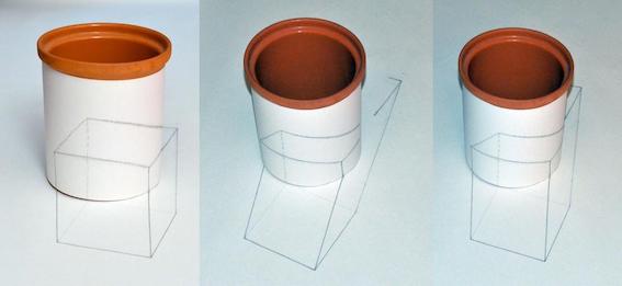
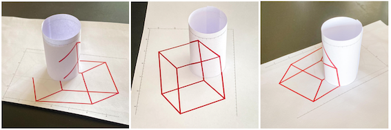
These are 3 different ViewPoint of the same setup:
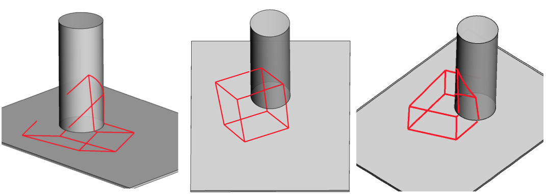
The cube can also be rotated:
To make a real 3D model of this, we need a printout of the part of the projection onto the xy plane and the development of the part on the cylinder. The next piece of code does this:
Module[{\[Alpha] = 0.5, \[Beta] = -0.33, \[Gamma] = 0.12, \[Rho] =
   2.25, \[Phi] = 45 \[Degree], cubeGC, edgeIndexes, ptsI, floorPts,
  cylPts, \[Theta], ptT1, ptT2, noGoZone},
 cubeGC = PolyhedronData["Cube", "GraphicsComplex"];
 edgeIndexes = PolyhedronData["Cube", "EdgeIndices"];
 ptsI = \[Rho] ParallelMap[{2.05, -.35, 1.75} +
      RollPitchYawMatrix[{\[Alpha], \[Beta], \[Gamma]}].#1 &, \
(interpol3D[#1, 20] &) /@ (cubeGC[[1]][[#1]] &) /@
      edgeIndexes, {2}]; \[Theta] = \[Pi]/2 - ArcSin[1/35];
 ptT1 = AngleVector[{1, \[Theta]}];
 ptT2 = AngleVector[{1, -\[Theta]}];
 noGoZone =
  Polygon[{{0, 0}, ptT1, ptT1 + 10 {-1, Cot[\[Theta]]},
    ptT2 + 10 {-1, -Cot[\[Theta]]}, ptT2}];
 floorPts = Map[floorPoint3D[#1, \[Phi], 35, 5] &, ptsI, {2}];
 cylPts = Map[cylinderPoint3D[#1, \[Phi], 35, 5] &, ptsI, {2}];
 GraphicsColumn[{Graphics[{{AbsoluteThickness[5], Red,
      Line /@ floorPts}, {FaceForm[White], EdgeForm[Dotted],
      noGoZone}, {Dotted, Gray, Circle[]}, White, Disk[]},
    Frame -> True, PlotRange -> {{-3, 4}, {-3.5`, 1.5`}}],
   Graphics[{AbsoluteThickness[5], Red, Line /@ cylPts},
    Frame -> True, PlotRange -> {{-3, 4}, {0, 3}}]}]]
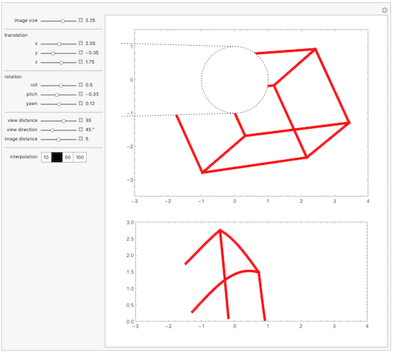
Printed on paper and rolled into the right radius cylinder, we get this:
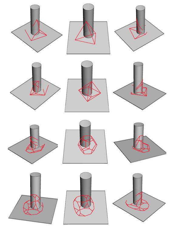
Other polyhedrons can be explored by using PolyhedronData:
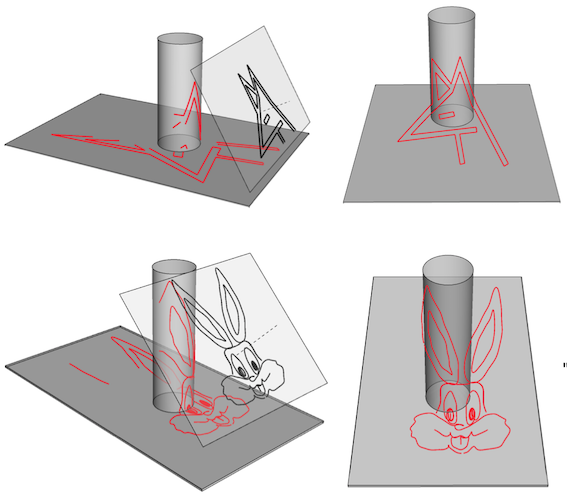
The same can be done with 2D images such as logos or cartoon figures:
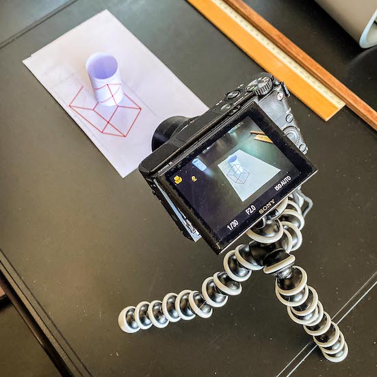
While in quarantine, you can do as I did and use the above functions to make your own anamorphic experimental setup! The attached notebook "anamorphic perspective.nb" contains all the code used. Have fun!
 Attachments:


